Cleaning apparatus for gas scrubber fluid

a technology of scrubber fluid and cleaning apparatus, which is applied in the nature of treatment water, centrifuges, separation processes, etc., can solve the problems of unacceptable release of polluted scrubber fluid directly into the sea, high cost and undesirable transport of large amounts of waste material to a harbour, and improve the efficiency of exhaust treatment procedures , the effect of minimizing the amount of was

Inactive Publication Date: 2013-06-20
ALFA LAVAL CORP AB
View PDF8 Cites 11 Cited by
  • Summary
  • Abstract
  • Description
  • Claims
  • Application Information

AI Technical Summary

Benefits of technology

[0009]The present invention reduces the above mentioned shortcomings by further improving environmental aspects of exhaust treatment procedures, improving the efficiency in exhaust treatment procedures, minimizing the amount of waste material that needs to be handled and disposed and further minimizing the need for service and diminishing problems with process equipment handling scrubber fluid.
[0010]Thus, the present invention relates to a cleaning apparatus for polluted scrubber fluid from an exhaust gas scrubber fluid loop. The scrubber fluid loop may be a closed scrubber fluid loop, i.e. a circulation system providing recirculation of scrubber fluid through the scrubber and other components within the system. The scrubber fluid loop may include scrubbers used to clean the full flow of exhaust gas from an engine and / or scrubbers used to clean part of the flow of exhaust gas from an engine, e.g. during EGR. The cleaning apparatus comprises means for bleeding off part of the polluted scrubber fluid from the scrubber fluid loop, thereby removing the part of the polluted scrubber fluid from the scrubber fluid loop for disposal. The part of the polluted scrubber fluid being bled off from the scrubber fluid loop is preferably a small part of the flow of the fluid within the scrubber fluid loop. By recirculating the polluted scrubber fluid in the scrubber fluid loop through the scrubber and only bleeding off a small part of the polluted scrubber fluid from the scrubber fluid loop, the amount of pollutant phase in the polluted scrubber fluid can reach a level so as to to maintain efficient separation of the pollutant phase while minimizing the volume of polluted fluid that has to be treated.

Problems solved by technology

Also in this process, polluted scrubber fluid is produced.
The release of such polluted scrubber fluid directly into the sea is unacceptable from an environmental point of view and is strictly regulated.
On the other hand, it is expensive and undesirable to transport larger amounts of waste material to a harbour for disposal.
One problem is then to improve the cleaning of the scrubber fluid in order to be able to release the scrubber fluid into the environment with a minimal environmental impact.
Another problem is the cleaning of the scrubber fluid in order to be able to fulfil regulations on the amount of polyaromatic hydrocarbons and turbidity in the scrubber fluid to be released into the environment.

Method used


Image

  • Cleaning apparatus for gas scrubber fluid
  • Cleaning apparatus for gas scrubber fluid
  • Cleaning apparatus for gas scrubber fluid

Examples


Embodiment Construction

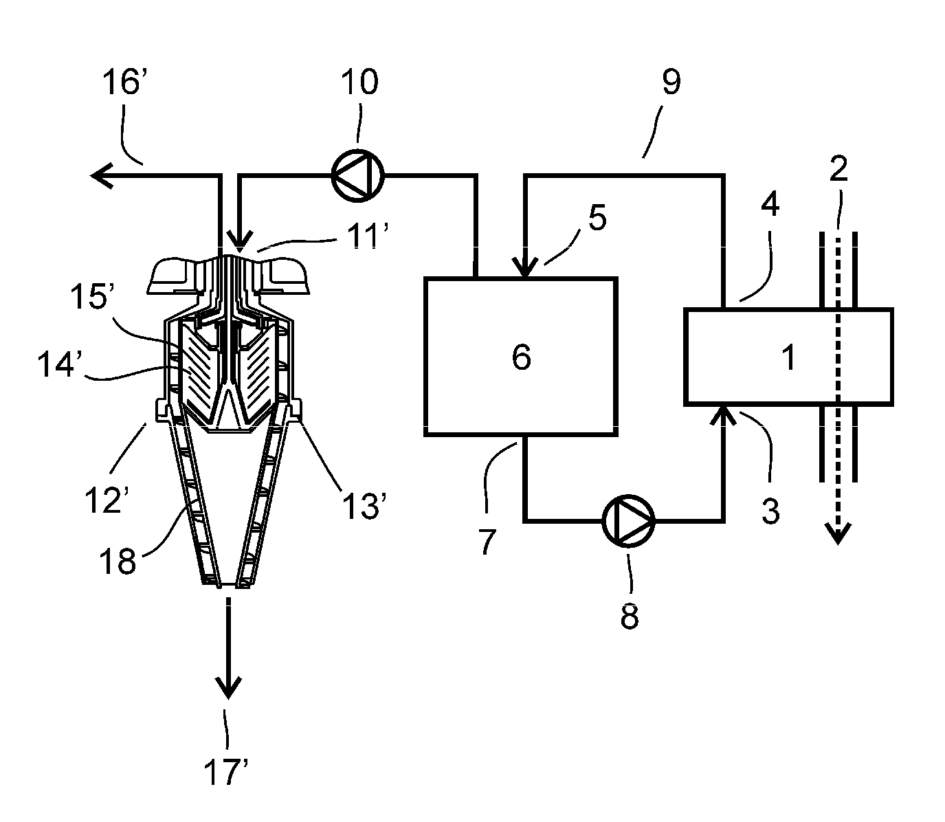
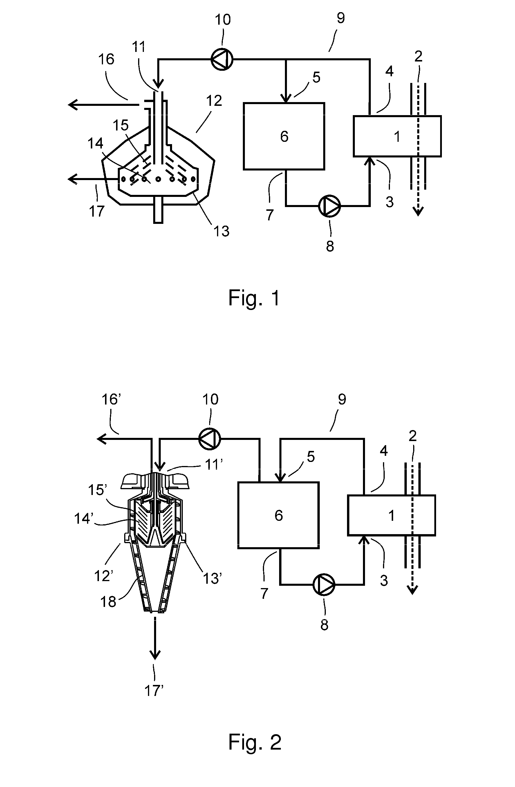
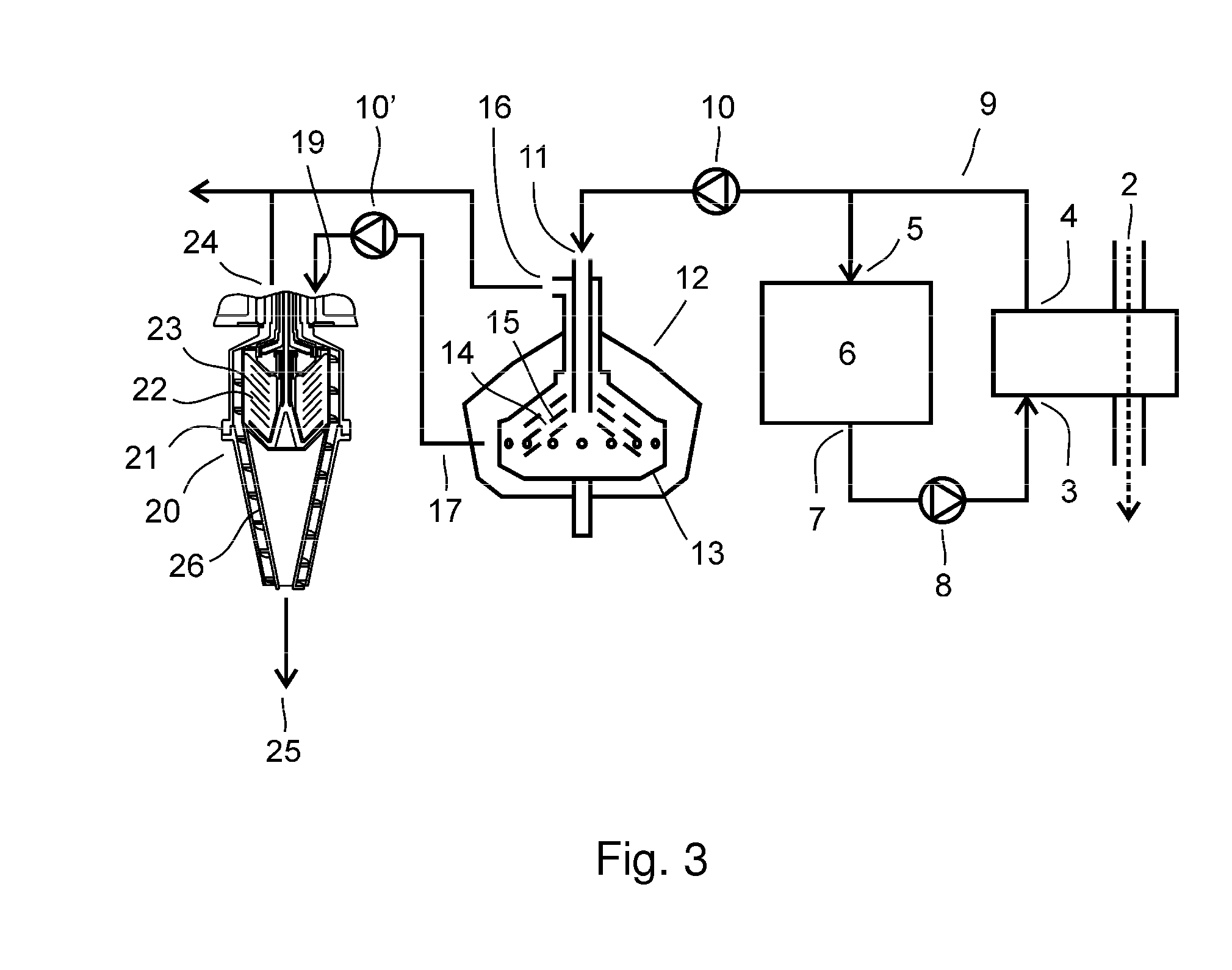
[0041]A cleaning apparatus for gas scrubber fluid is shown in FIG. 1, connected to an exhaust gas scrubber 1. The exhaust gas scrubber 1 acts on an exhaust conduit 2 of a large diesel engine, such as the main or auxiliary engine of a ship. The scrubber is provided with a scrubber inlet 3 and a scrubber outlet 4 for scrubber fluid. The scrubber outlet 4 is connected to an inlet 5 of a buffer tank 6 for scrubber fluid. The buffer tank further comprises an outlet 7 for providing scrubber fluid to the inlet 3 of the scrubber, via a scrubber feed pump 8. The scrubber 1, the buffer tank 6 and the tubing connecting them form a closed scrubber fluid loop 9 in which scrubber fluid is being circulated during operation. The scrubber fluid loop may further be provided with means for the addition of clean scrubber fluid, such as tap water, fresh water or desalinated seawater to the process during operation (not shown). This may be done in any part of the scrubber fluid loop 9.

[0042]The cleaning ...


PUM

PropertyMeasurementUnit
pHaaaaaaaaaa
rotational speedaaaaaaaaaa
centrifugal forceaaaaaaaaaa

Abstract

A cleaning apparatus for polluted scrubber fluid from an exhaust gas scrubber fluid loop includes means for bleeding off part of the polluted scrubber fluid from the scrubber fluid loop, a disc stack centrifugal separator for separating a pollutant phase and a cleaned scrubber fluid from said part. The separator includes a rotor enclosing a separation space with a stack of separating discs, a separator inlet extends into the separating space, a first separator outlet for cleaned scrubber fluid extending from said separating space, and a second separator outlet for the pollutant phase extending from the separating space. The cleaning apparatus includes means for conducting the part to the separator inlet, and means for discharging the cleaned scrubber fluid from the first separator outlet, and means for collecting the pollutant phase from the second separator outlet.

Description

TECHNICAL FIELD[0001]The present invention relates to a cleaning apparatus for gas scrubber fluid and to the use of a disc stack centrifugal separator in such a cleaning apparatus.BACKGROUND OF THE INVENTION[0002]The shipping industry of today strives to reduce harmful emissions, such as emissions originating from the combustion of fuel in the engines, in order to minimize the negative environmental impact and fulfil present and upcoming emission regulations, such as regulations set up by the International Maritime Organization (IMO).[0003]One object of the emissions regulations is the reduction in sulphuric oxide (SOX) emissions from ships. Sulphuric oxides are created in the combustion of fuels containing sulphuric residues. The amount of sulphuric oxides in exhaust gas can be reduced by exhaust gas cleaning, e.g. by using scrubbers. The process of cleaning exhaust gas with the aid of the mentioned scrubbers produces polluted scrubber fluid.[0004]Another object of the emissions re...

Claims


Application Information

Patent Timeline
Patent Type & Authority Applications(United States)
IPC IPC(8): B01D19/00
CPCB01D53/50B01D53/96B04B5/10C02F1/385C02F1/56B01D19/0057C02F2103/008C02F2103/18C02F2209/06C02F2301/043C02F1/66Y02T10/12C02F1/38B01D47/00B04B1/00B01D53/14
Inventor KONIGSSON, STAFFANSUNDQUIST, LENA
Owner ALFA LAVAL CORP AB
Why Eureka
Try Eureka