Aircraft air conditioning system comprising a separate refrigeration cycle

a refrigeration cycle and air conditioning system technology, applied in the field of air conditioning systems for aircraft, can solve the problems of unfavorable heat emission and system air supply, and achieve the effects of reducing the length of hot bleed air ducts for the air supply of the air-conditioning system, reducing the dimensions of the system and its weight, and reducing the transfer of hot air within the air-conditioning system

Active Publication Date: 2013-06-27
AIRBUS OPERATIONS GMBH
View PDF37 Cites 39 Cited by
  • Summary
  • Abstract
  • Description
  • Claims
  • Application Information

AI Technical Summary

Benefits of technology

[0007]One embodiment of the invention includes an air-conditioning system comprising a compressed air branch for conveying externally supplied and pressurized air, a cooling circuit for conveying refrigerant that extends through a ram air duct, a first heat exchanger for the heat transfer between the compressed air branch and the cooling circuit, a compressed air turbine that is arranged in the compressed air branch, as well as a cooling circuit compressor that is arranged in the cooling circuit and mechanically coupled to the compressed air turbine. Due to this design, a hybrid air cooling system for a passenger aircraft is created, in which a fresh air supply is combined with another cooling system. Due to the division into the compressed air branch and the separate cooling circuit, the air-conditioning system can be divided into modules that can be flexibly positioned and arranged at different locations in the aircraft, wherein a ram air duct may, for example, be arranged in the belly of the aircraft and the air-conditioning unit with the heat exchanger for cooling the bleed air may be arranged in the tail section of the aircraft, or wherein the turbine and compressor unit may be separated from the ram air cooling circuit. Consequently, the heat exchangers for cooling the hot bleed air can be positioned as close as possible to the engines and therefore the bleed air withdrawal point such that the length of hot bleed air ducts for the air su...

Problems solved by technology

Consequently, the duct system for the air supply in the aircraft may, if so required, have to be installed over great distances.
However, such a heat emission is not advantageous due to the separation into pressurized and unpressurized zones and the associated large bulges in the pressurized aircraft fuselage.
In addition to the disadvantageou...

Method used


Image

  • Aircraft air conditioning system comprising a separate refrigeration cycle
  • Aircraft air conditioning system comprising a separate refrigeration cycle
  • Aircraft air conditioning system comprising a separate refrigeration cycle

Examples


Embodiment Construction

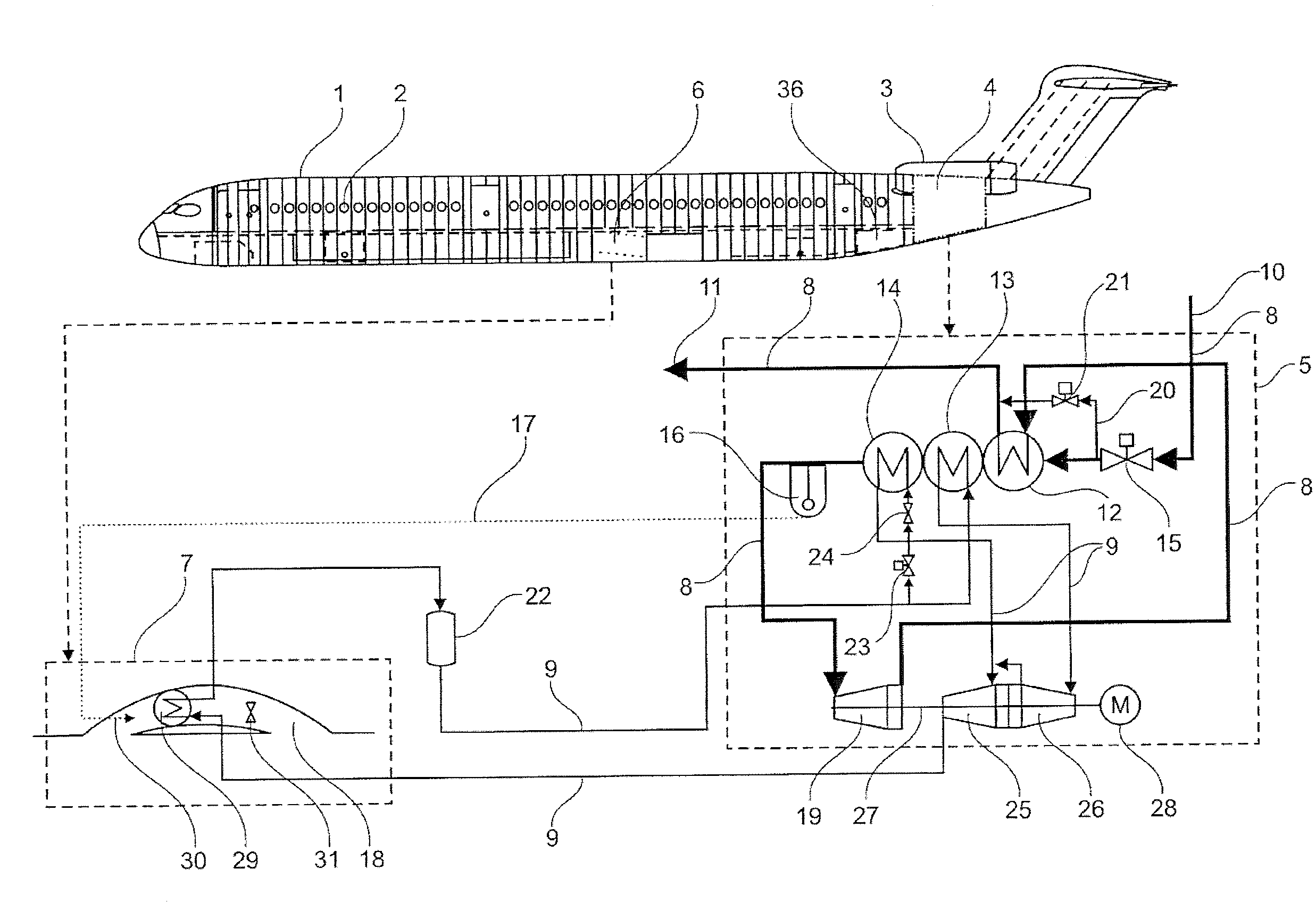
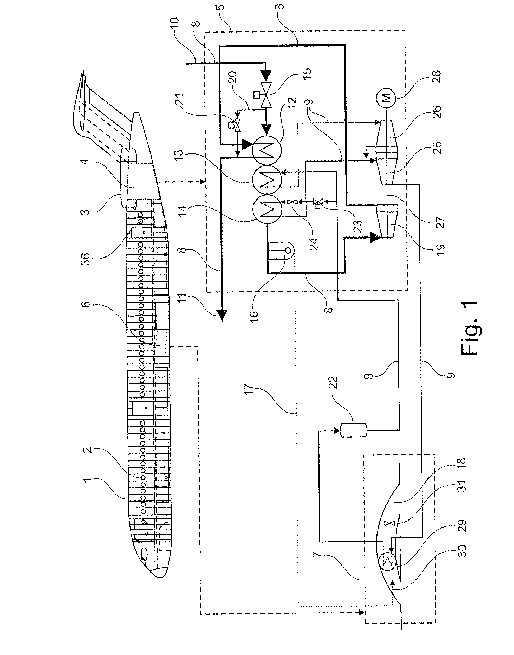
[0024]Other features, advantages and possible applications of the present invention result from the following detailed description of preferred exemplary embodiments and the figures. In this respect, all described and / or graphically illustrated characteristics form aspects of the invention individually and in arbitrary combination—namely regardless of their concretely claimed combination or references of the claims to other claims. In the figures, identical or similar elements are furthermore identified by the same reference symbols. Specifications such as “upstream,”“downstream,”“preceding” or “following” respectively refer to the intended fluid flow direction in the respective compressed air branch, refrigerant circuit or ram air duct.

[0025]FIG. 1 shows a schematic design of the air-conditioning system for an aircraft. In this illustration, this aircraft is represented by an airplane 1 with a pressurized cabin 2 and engines 3. Two air-conditioning units 5 are arranged in a tail se...


PUM


Abstract

An air-conditioning system for an aircraft includes a compressed air branch for conveying externally supplied and pressurized air, preferably bleed air. Furthermore, a cooling circuit for conveying preferably liquid refrigerant is provided and extends through a ram air duct. The system also includes a first heat exchanger for the heat transfer between the compressed air branch and the cooling circuit, a compressed air turbine arranged in the compressed air branch and a cooling circuit compressor arranged in the cooling circuit and mechanically coupled to the compressed air turbine. The system can have a modular design and be positioned at optimal locations in the aircraft due to the separation of the compressed air branch and the cooling circuit. In this way, the length of hot compressed air ducts can be shortened.

Description

CROSS-REFERENCE TO RELATED APPLICATIONS[0001]The present application is a continuation of International Application No. PCT / EP2011 / 064120, filed on Aug. 17, 2011, which claims priority from German Patent Application No. 10 2010 034 830.9 filed Aug. 19, 2010, and which claims the benefit of the filing date of U.S. Provisional Patent Application No. 61 / 375,087, filed on Aug. 19, 2010, the disclosures of which are hereby incorporated herein by reference.FIELD OF THE INVENTION[0002]The invention pertains to an air-conditioning system for an aircraft, a method for air-conditioning an aircraft and an aircraft with such an air-conditioning system.TECHNOLOGICAL BACKGROUND[0003]Air-conditioning systems in aircraft are usually supplied with bleed air in the form of hot compressed air that is withdrawn from a compressor stage of an engine or obtained with the aid of a compressor that is driven by an auxiliary gas turbine (“APU”). Such an air-conditioning system is known, for example, from DE 1...

Claims


Application Information

Patent Timeline
IPC IPC(8): F25B9/06
CPCB64D13/08B64D2013/064B64D2013/0674Y02T50/44Y02T50/56F25B9/06B64D2013/0688Y02T50/50Y02T50/40
Inventor KLIMPEL, FRANKSCHMIDT, STEPHAN-ANTONBEIER, JENS
Owner AIRBUS OPERATIONS GMBH
Why Eureka
Try Eureka