Vacuum Processing Apparatus

a technology of vacuum processing and vacuum chamber, which is applied in the direction of vacuum evaporation coating, electrolysis components, coatings, etc., can solve the problems of large system size, large number of parts, and high cost, and achieve the effect of high vacuum and efficient cooling

Active Publication Date: 2013-07-04
ULVAC INC
View PDF5 Cites 7 Cited by
  • Summary
  • Abstract
  • Description
  • Claims
  • Application Information

AI Technical Summary

Benefits of technology

[0012]Accordingly, preferably a cooling panel is disposed so as to face the sheet base material on an upstream side of the take-up roller. Then, the surface of the cooling panel which faces the sheet base material functions as a heat absorbing surface. Thus, the sheet base material can be efficiently cooled. Also, in the case where the cooling panel is, for example, a cryopanel maintained at an extremely low temperature (several tens of K, water and the like in the auxiliary vacuum chamber are adsorbed by the panel, and this contributes to maintaining a high degree of vacuum in the auxiliary vacuum chamber. This is advantageous because, for example, a low-cost pump having a low pumping capacity may be employed as a pump to be provided in the auxiliary vacuum chamber.

Problems solved by technology

However, in the above-described apparatus of the known example, since the front and back surfaces of the sheet base material are processed in the separate processing chambers, the system itself becomes large in size, and also requires a large number of parts, which leads to high cost.
Further, the productivity is low since the apparatus has a long path along which the sheet base material fed from the feed roller is passed through the two vacuum processing chambers and is then wound around the take-up roller.

Method used


Image

  • Vacuum Processing Apparatus
  • Vacuum Processing Apparatus
  • Vacuum Processing Apparatus

Examples


Embodiment Construction

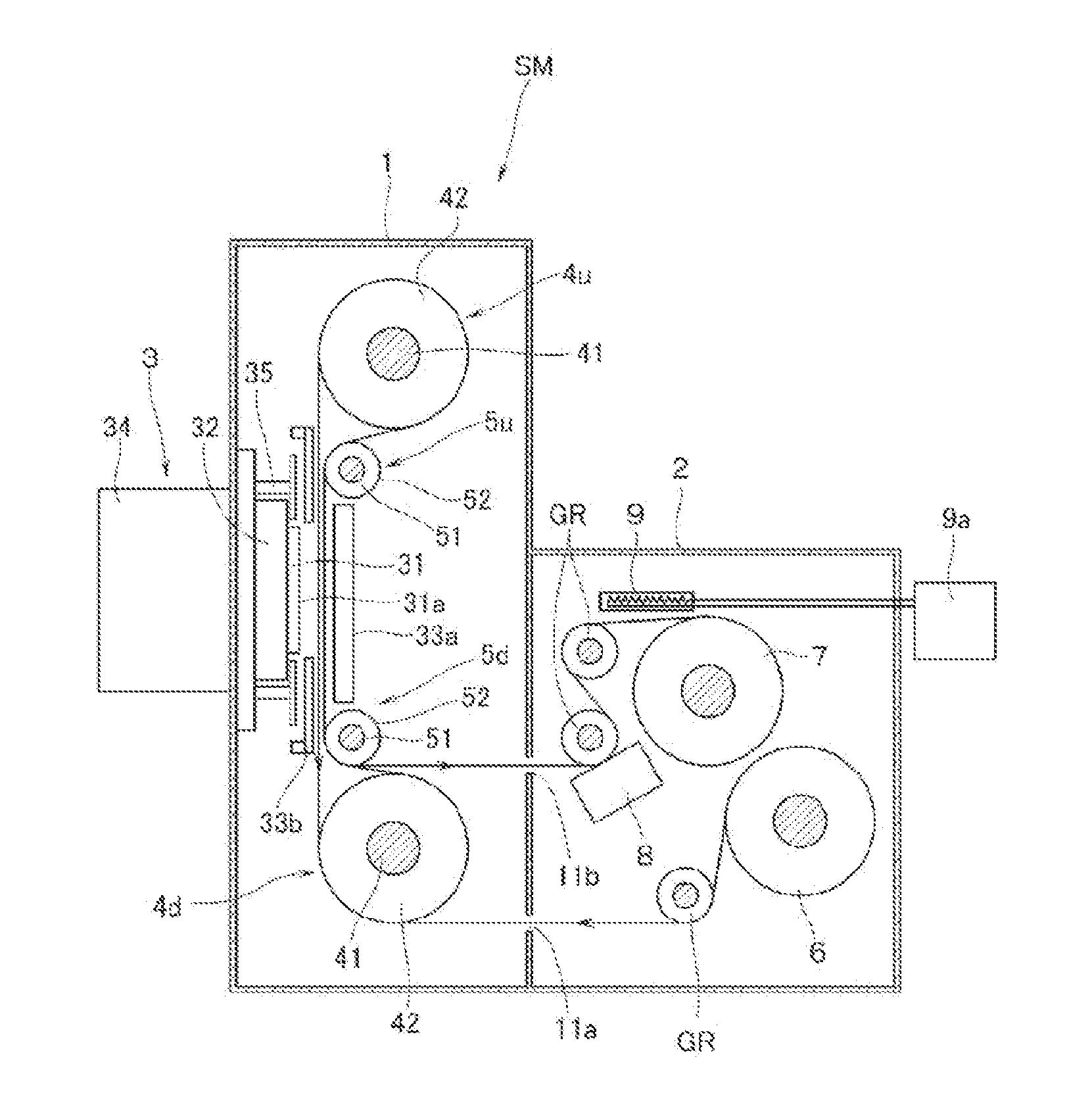
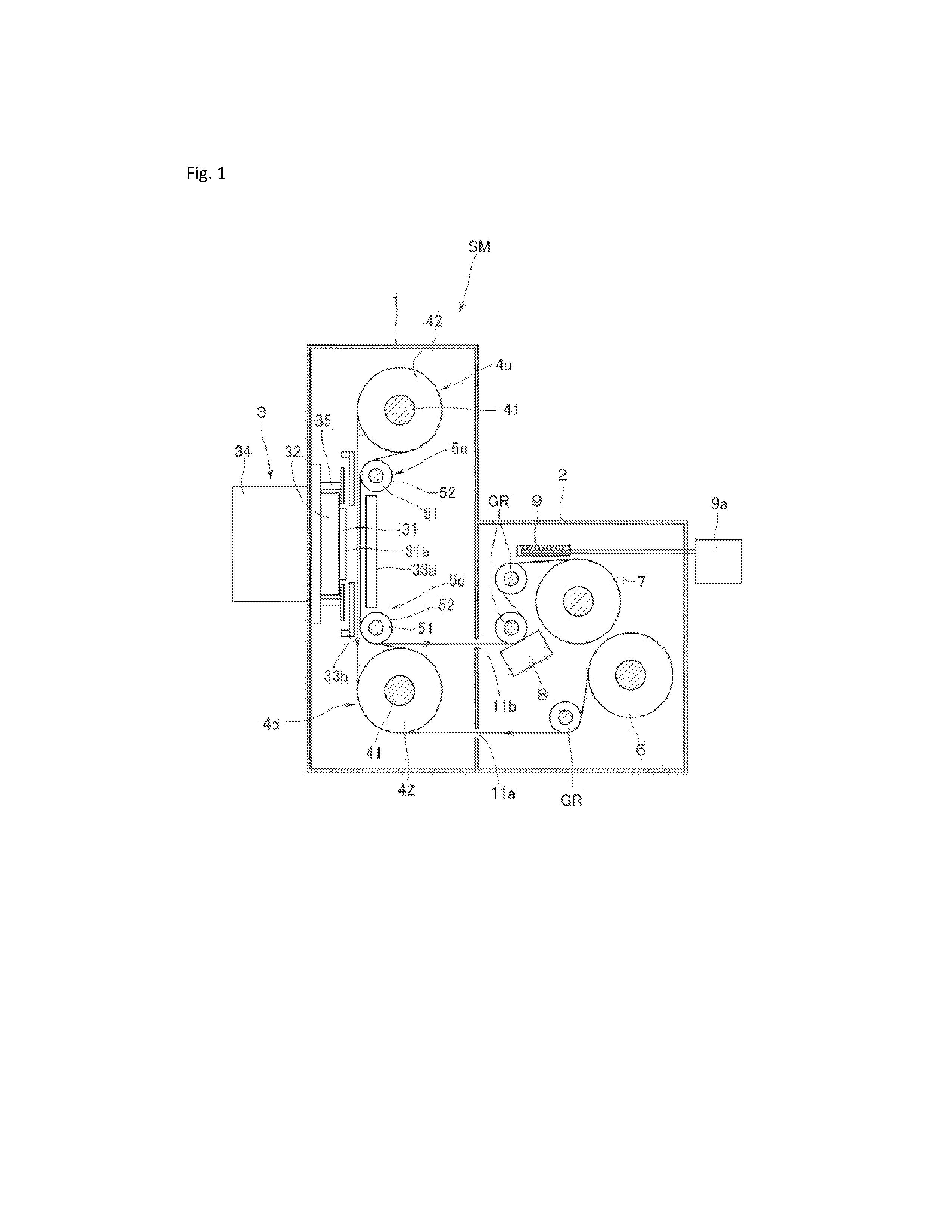
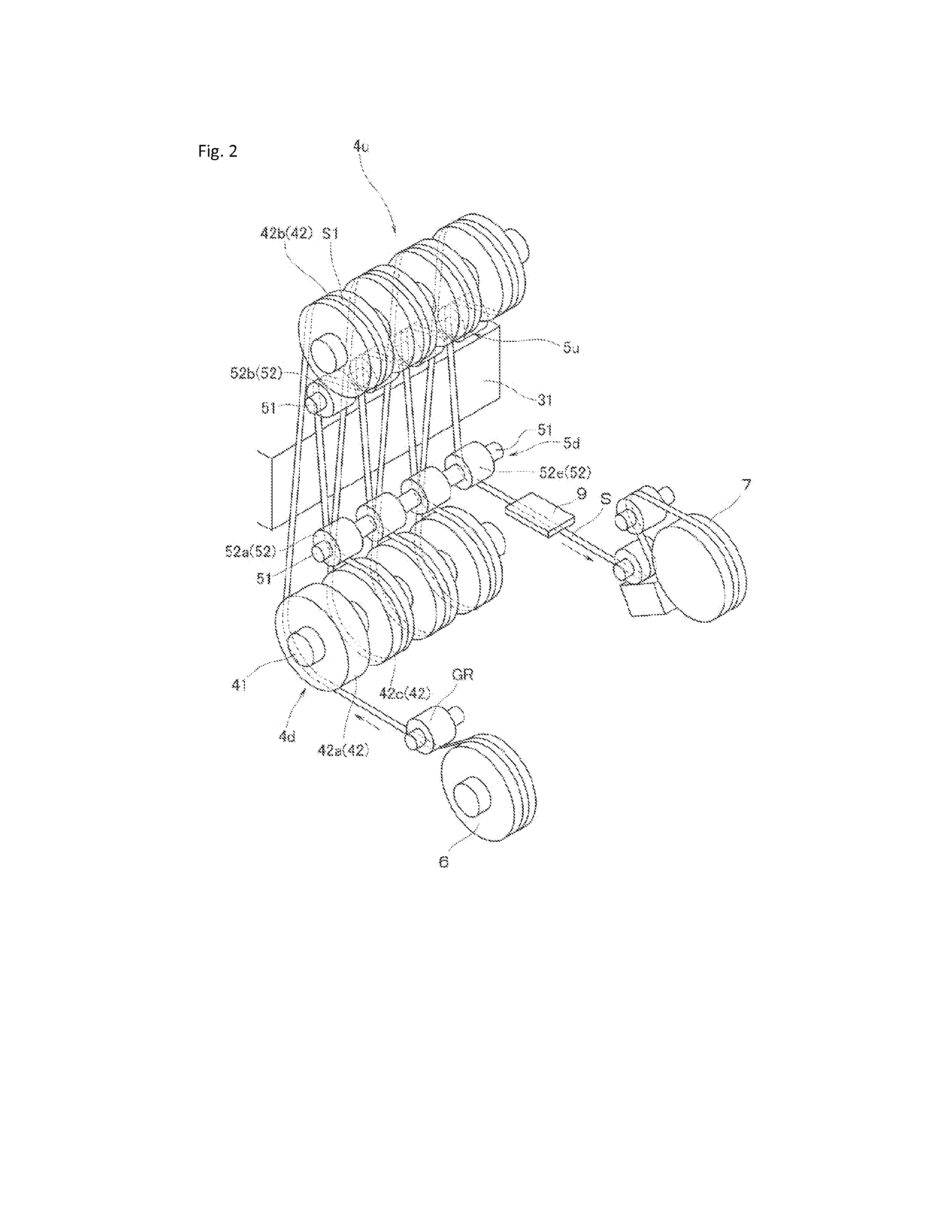
[0016]Hereinafter, with reference to the drawings, a vacuum processing apparatus of an embodiment of this invention will be described by taking as an example the case where a processing unit is a cathode unit for film deposition by sputtering and where a film is formed on each of front and back surfaces of a sheet base material.

[0017]Referring to FIGS. 1 and 2, SM denotes the vacuum processing apparatus of this embodiment. This vacuum processing apparatus SM includes a vacuum processing chamber 1 having a rectangular parallelepiped shape evacuated to a vacuum by a vacuum pump (not illustrated), and an auxiliary vacuum chamber 2 provided in continuation with one side surface of the vacuum processing chamber 1. A sheet base material S is transported from the auxiliary vacuum chamber 2 through the vacuum processing chamber 1, and a film can be formed on the sheet base material S in the vacuum processing chamber 1. A single cathode unit 3 is mounted on that another side surface of the v...


PUM

PropertyMeasurementUnit
timeaaaaaaaaaa
distanceaaaaaaaaaa
widthaaaaaaaaaa

Abstract

Provided is a low-cost vacuum processing apparatus which enables the miniaturization of the apparatus and achieves good productivity. An elongated sheet base material is transported through a vacuum processing chamber, and predetermined processing is performed on the sheet base material in this vacuum processing chamber. The vacuum processing chamber is provided with a single processing unit, and has an auxiliary vacuum chamber provided in continuation with the vacuum processing chamber. The auxiliary vacuum chamber is provided with a feed roller and a take-up roller. The vacuum processing apparatus includes a pair of first roller units provided on opposite sides across the processing unit in the vacuum processing chamber. Each of the first roller units has multiple rollers disposed at regular distances. The rollers are deviated from each other in the axial direction and arranged in such a staggered manner that the sheet base material is helically wound around the rollers.

Description

TECHNICAL FIELD[0001]The present invention relates to a vacuum processing apparatus for performing predetermined processing in a vacuum processing chamber on an elongated sheet base material by transporting it through the vacuum processing chamber.BACKGROUND ART[0002]Elongated sheet base materials made of resin have flexibility and good processability, and is accordingly publicly known to be used to fabricate electronic parts or optical components by the steps of forming a predetermined thin film such as a predetermined metal or oxide film on surfaces of the elongated sheet base materials, performing heat treatment or plasma processing thereof, and the like. Depending on the use of an elongated sheet base material, the same predetermined processing may be performed on both of the front and back surfaces of the sheet base material.[0003]As an apparatus for performing predetermined processing on both of the front and back surfaces of such a sheet base material, there has been kwon an ...

Claims


Application Information

Patent Timeline
Patent Type & Authority Applications(United States)
IPC IPC(8): C23C14/34
CPCC23C14/50C23C14/34C23C14/562C23C14/56
Inventor HIRONO, TAKAYOSHITADA, ISAO
Owner ULVAC INC
Why Eureka
Try Eureka