
Method for producing a piston ring

a technology of piston rings and rings, applied in the direction of piston rings, engine components, mechanical apparatus, etc., can solve the problems of undesired change in ring high internal stresses, and affecting the shape and radial pressure distribution of rings,

Inactive Publication Date: 2013-07-11
FEDERAL MOGUL BURSCHEID
View PDF2 Cites 8 Cited by
  • Summary
  • Abstract
  • Description
  • Claims
  • Application Information

AI Technical Summary

Benefits of technology

The patent describes a method for machining the inner surface of a piston ring to improve its performance. The method involves first overlapping the ends of the piston ring using a final cylindrical lapping process. Then, the inner surface of the piston ring is machined from the butt joint ends in both directions, starting from the butt joint. This method reduces wear and friction on the running surface, improves the lapping result, and amplifies the effect of a nitriding layer with internal compressive stresses. The reduced radial butt joint pressure at the end of the machining process also has a positive effect on the lapping process and the tribological behavior of the running surface. Overall, this method improves the performance of piston rings.

Problems solved by technology

This degree of hardness brings high internal stresses, which may affect the ring shape and the radial pressure distribution.
Both during manufacture and when used in an engine, these high internal stresses generate an undesired change in the ring shape and radial pressure distribution.
This in turn leads to increased wear on the running surface, particularly in this area.
However, particularly in connection with compression piston rings made from profiled wire, this method is not workable from a manufacturing point of view.
Due to the butt joint play and butt joint play tolerances becoming ever narrower, the technical efficacy of generating negative ovalities in order to counter the high internal stresses cannot be economically implemented since the lapping bushing already must be replaced after a very short period of time.

Method used


Image

  • Method for producing a piston ring
  • Method for producing a piston ring

Examples


Embodiment Construction

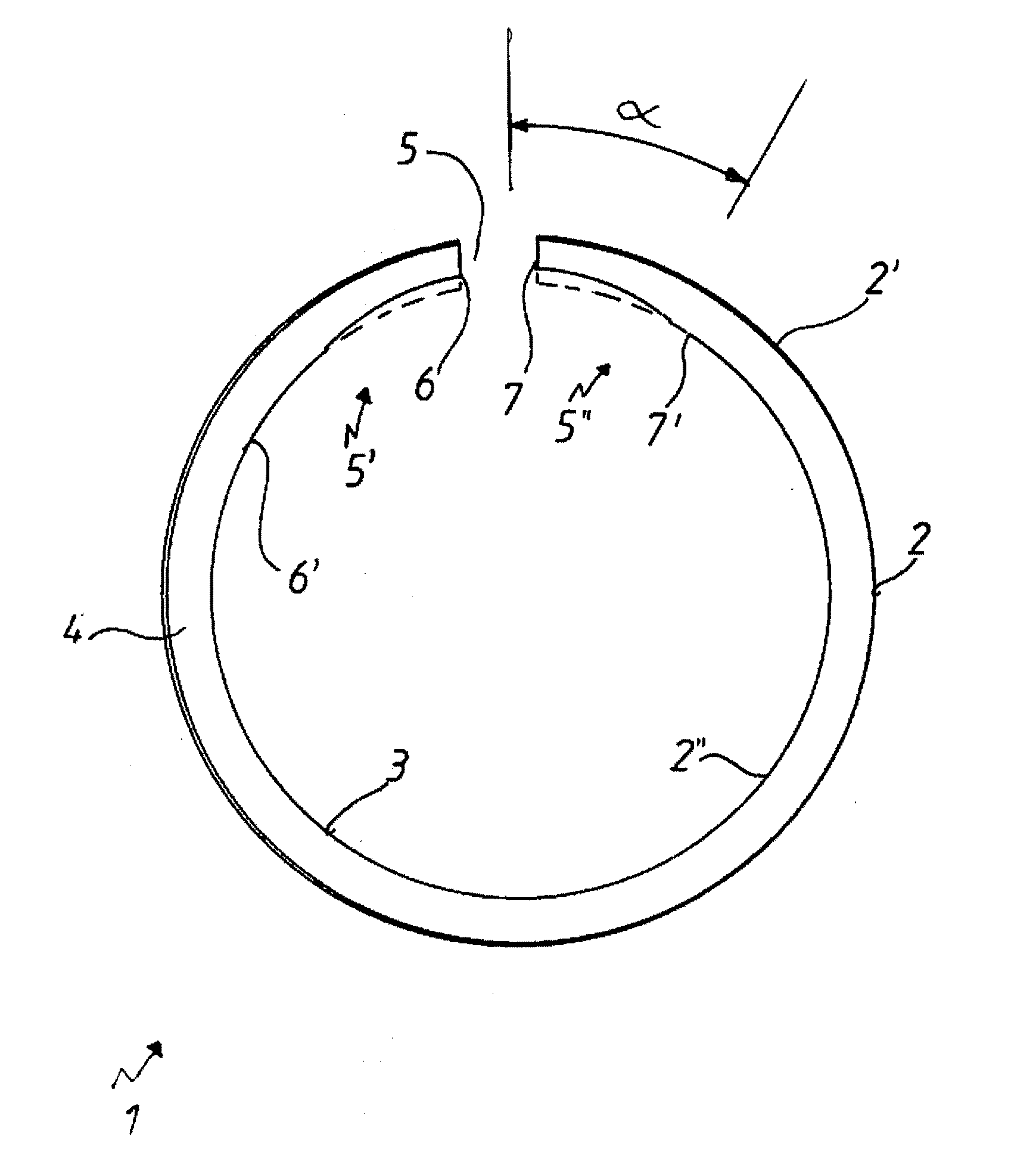
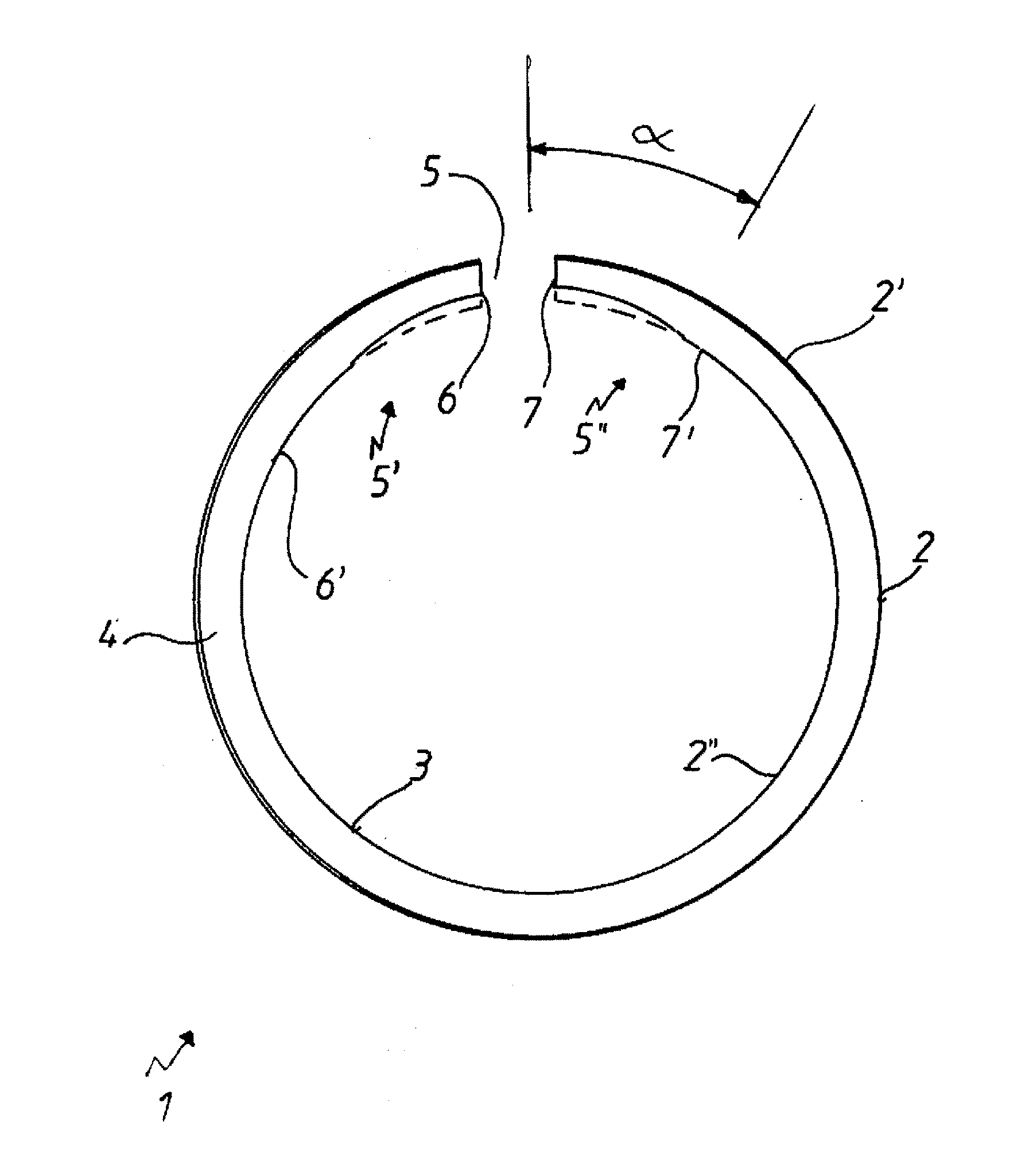
[0020]The piston ring 1, in particular a compression piston ring, shown in the drawing has a running surface 2, an inner circumferential surface 3, and an upper ring flank 4. The piston ring 1 additionally has a butt joint 5. In this example, the piston ring 1 is to be provided with a PVD layer 2′ applied onto the running surface 2. As already mentioned, such hard running surface layers affect the internal stress of the piston ring 1, and do so particularly in terms of the fact that the (softer) base material of the piston ring 1 and the (harder) PVD have different thermal expansions that have a negative effect on the butt joint area 5 in particular. This means that the butt joint area 5 springs radially outward, and therefore, generates in this area an increased contact pressure force on the friction partner, for example, a cylinder liner. In order to counteract this negative effect, it is proposed, according to the invention, after the surface coating of the piston ring, in partic...


PUM

PropertyMeasurementUnit
Angleaaaaaaaaaa
Angleaaaaaaaaaa
Thicknessaaaaaaaaaa

Abstract

Method for producing a piston ring provided with a butt joint, in that an annular metallic main body is provided with at least one hard layer at least in the area of the outer circumferential surface of said main body, wherein after this coating the inner circumferential surface of the piston ring is at least partially subjected to a wall-thickness-reducing material removal process.

Description

BACKGROUND OF THE INVENTION[0001]The invention relates to a method for producing a piston ring provided with a butt joint.[0002]Due to increasing power density in both gasoline engines and diesel engines, the load on the piston ring, with regard to wear- and temperature-resistance, increases to the same extent. In order to counteract this, piston rings, which are chromed or nitrided on the running surface and which already entail a high degree of hardness, are being frequently produced. Piston rings that include very hard layer systems, such as PVD (Physical Vapor Deposition) or HVOF (High Velocity Oxygen Fuel) layers, for example, are also being used, again with regard to the aforementioned power density. This degree of hardness brings high internal stresses, which may affect the ring shape and the radial pressure distribution.[0003]Both during manufacture and when used in an engine, these high internal stresses generate an undesired change in the ring shape and radial pressure dis...

Claims


Application Information

Patent Timeline
IPC IPC(8): B23P15/06
CPCB23P15/06F16J9/00F16J9/14F16J9/26Y10T29/49281F02F5/00
Inventor MEYER, KLAUS
Owner FEDERAL MOGUL BURSCHEID
Learn More