Soft Start Circuit and Power Supply Device Using the Same

Inactive Publication Date: 2013-07-11
RALINK TECHNOLOGY CORP
View PDF13 Cites 14 Cited by
  • Summary
  • Abstract
  • Description
  • Claims
  • Application Information

AI Technical Summary

Benefits of technology

[0014]It is therefore an objective of the present invention to provide a soft start circuit and power supply device using the sam

Problems solved by technology

Therefore, since the voltage across the output capacitor C is zero or low during the activation period, a large inrush current occurs and thus damages devices.
Howe

Method used


Image

  • Soft Start Circuit and Power Supply Device Using the Same
  • Soft Start Circuit and Power Supply Device Using the Same
  • Soft Start Circuit and Power Supply Device Using the Same

Examples


Embodiment Construction

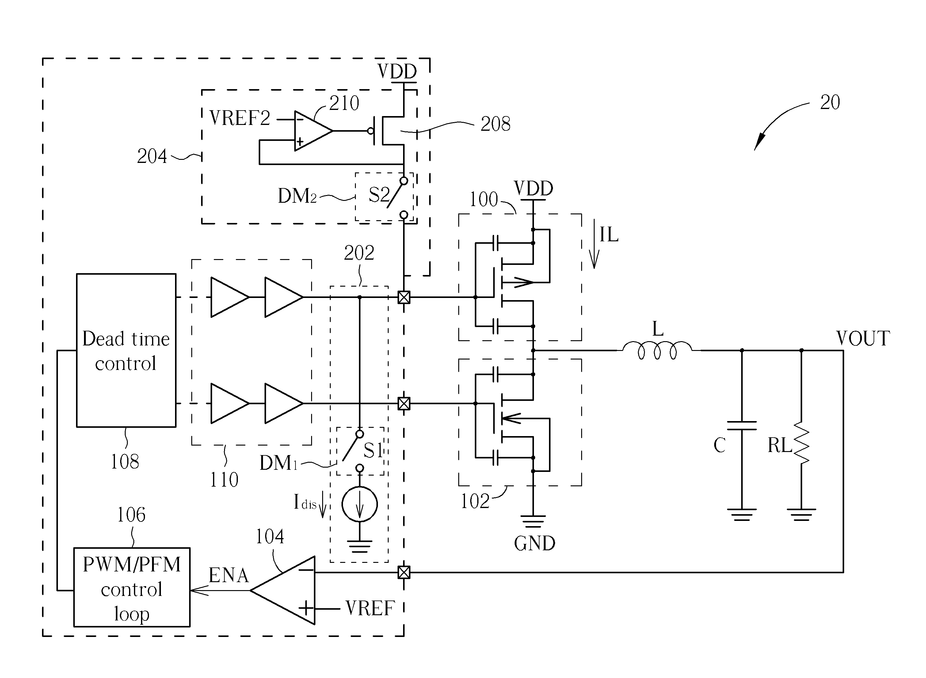
[0023]Please refer to FIG. 2A, which is a schematic diagram of a DC-DC switching regulator 20 according to an embodiment of the present invention. The structure and operating principles of the DC-DC switching regulator 20 are similar to those of the DC-DC switching regulator 10, such that elements and signals with similar functions are denoted with the same symbols for simplicity. Differences between the DC-DC switching regulator 20 and the DC-DC switching regulator 10 are that the DC-DC switching regulator 20 includes soft start circuits 202 and 204. The soft start circuit 202 discharges an equivalent total parasitic capacitor of the external P-type transistor 100 during an activation period, and the soft start circuit 204 clamps a voltage PWMP of the equivalent total parasitic capacitor, i.e. a gate voltage of the external P-type transistor 100, higher than or equal to a reference voltage VREF2 during the activation period. Noticeably, the equivalent total parasitic capacitor is e...


PUM


Abstract

The present invention discloses a soft start circuit for a power supply device comprising an external P-type transistor for charging an output capacitor to provide an output voltage. The soft start circuit includes a current source, for providing a discharge current; and a disabling means, coupled to the current source, for discharging an equivalent total parasitic capacitor of the external P-type transistor during an activation period according to the discharge current.

Description

BACKGROUND OF THE INVENTION[0001]1. Field of the Invention[0002]The present invention relates to a soft start circuit and power supply device using the same, and more particularly, to a soft start circuit and power supply device using the same capable of effectively reducing inrush current during an activation period without increasing chip area or requiring extra pins.[0003]2. Description of the Prior Art[0004]Power supply devices play an essential role in modern information technology. Among all the power supply devices, DC-DC switching regulators are very popular and are widely used for providing regulated DC power sources to electronic components.[0005]Please refer to FIG. 1A, which is a schematic diagram of a conventional DC-DC switching regulator 10. The DC-DC switching regulator 10 provides a steady output voltage VOUT to a load RL, and includes an external P-type transistor 100, an external N-type transistor 102, an inductor L, an output capacitor C, a comparator 104, a puls...

Claims


Application Information

Patent Timeline
IPC IPC(8): G05F1/46
CPCH02M1/36Y02B70/1466H02M3/1588Y02B70/10
Inventor LI, CHIH-CHENCHEN, CHIN-HSUN
Owner RALINK TECHNOLOGY CORP
Why Eureka
Try Eureka