
Microwave introducing mechanism, microwave plasma source and microwave plasma processing apparatus

a technology of plasma processing apparatus and microwave plasma, which is applied in the direction of plasma technique, chemical vapor deposition coating, coating, etc., can solve the problems of unfavorable slug tuner mobility, antenna and/or microwave transmitting plate temperature rise, etc., and achieve the effect of suppressing the heat effect on the mobility of slugs

Active Publication Date: 2013-07-18
TOKYO ELECTRON LTD
View PDF4 Cites 4 Cited by
  • Summary
  • Abstract
  • Description
  • Claims
  • Application Information

AI Technical Summary

Benefits of technology

This patent is about a new system that can use microwaves to create plasmas without heating up the movement of particles. This is useful in processing materials with microwaves.

Problems solved by technology

However, in such a microwave plasma source, if a microwave power applied is increased, the temperature of an antenna and / or a microwave transmitting plate rises due to the heat transferred from the plasma and the heat caused by microwave loss.
These heats may have an undesirable impact on the mobility of the slugs in a slug tuner.

Method used


Image

  • Microwave introducing mechanism, microwave plasma source and microwave plasma processing apparatus
  • Microwave introducing mechanism, microwave plasma source and microwave plasma processing apparatus
  • Microwave introducing mechanism, microwave plasma source and microwave plasma processing apparatus

Examples


Embodiment Construction

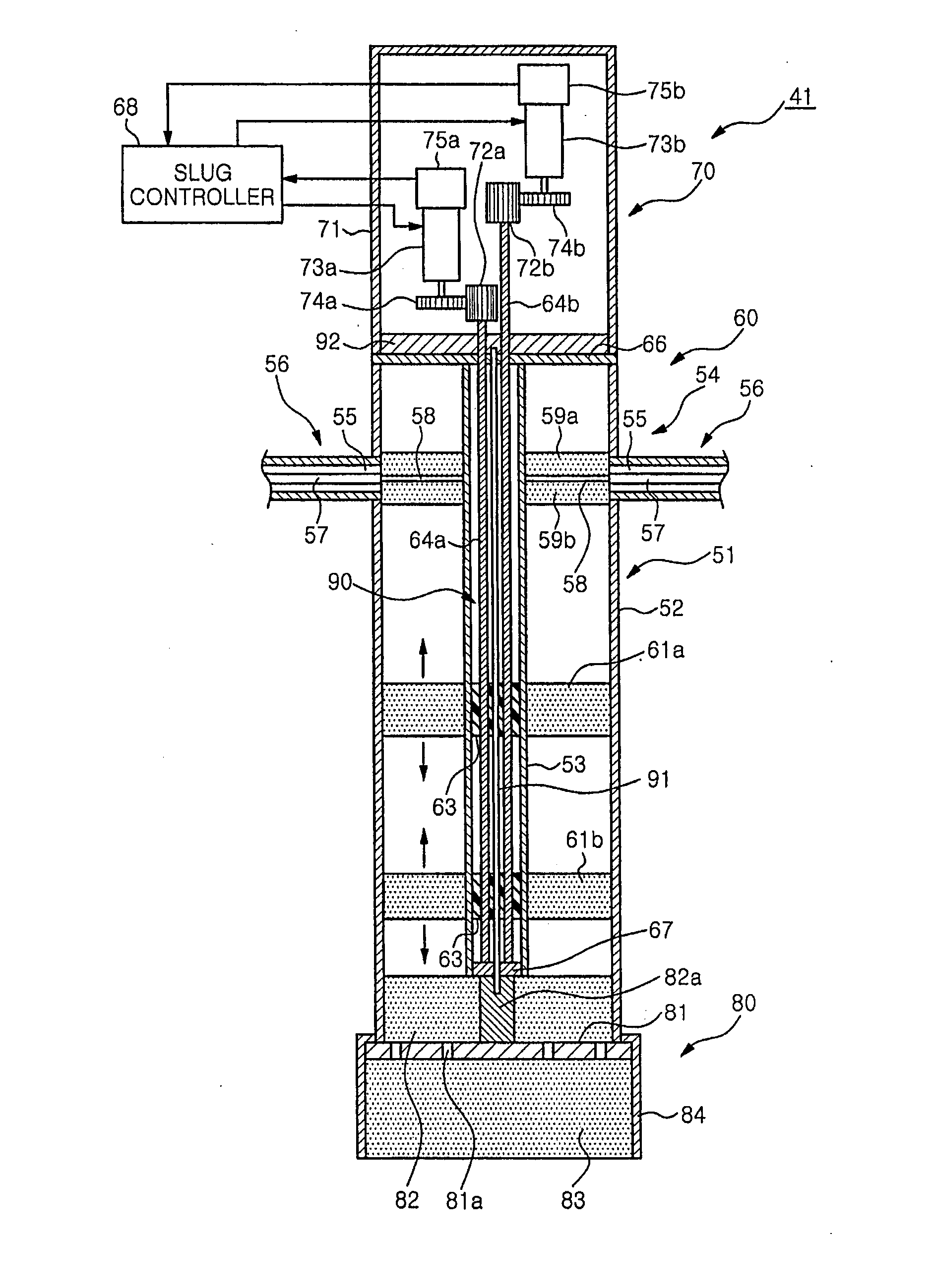
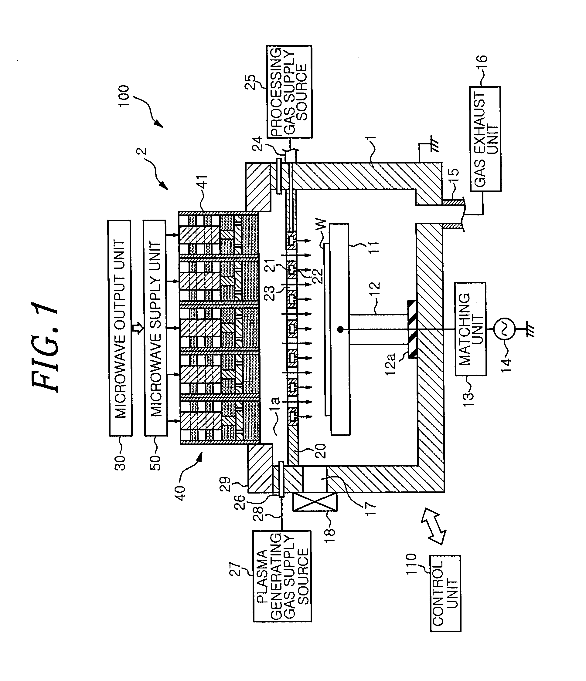
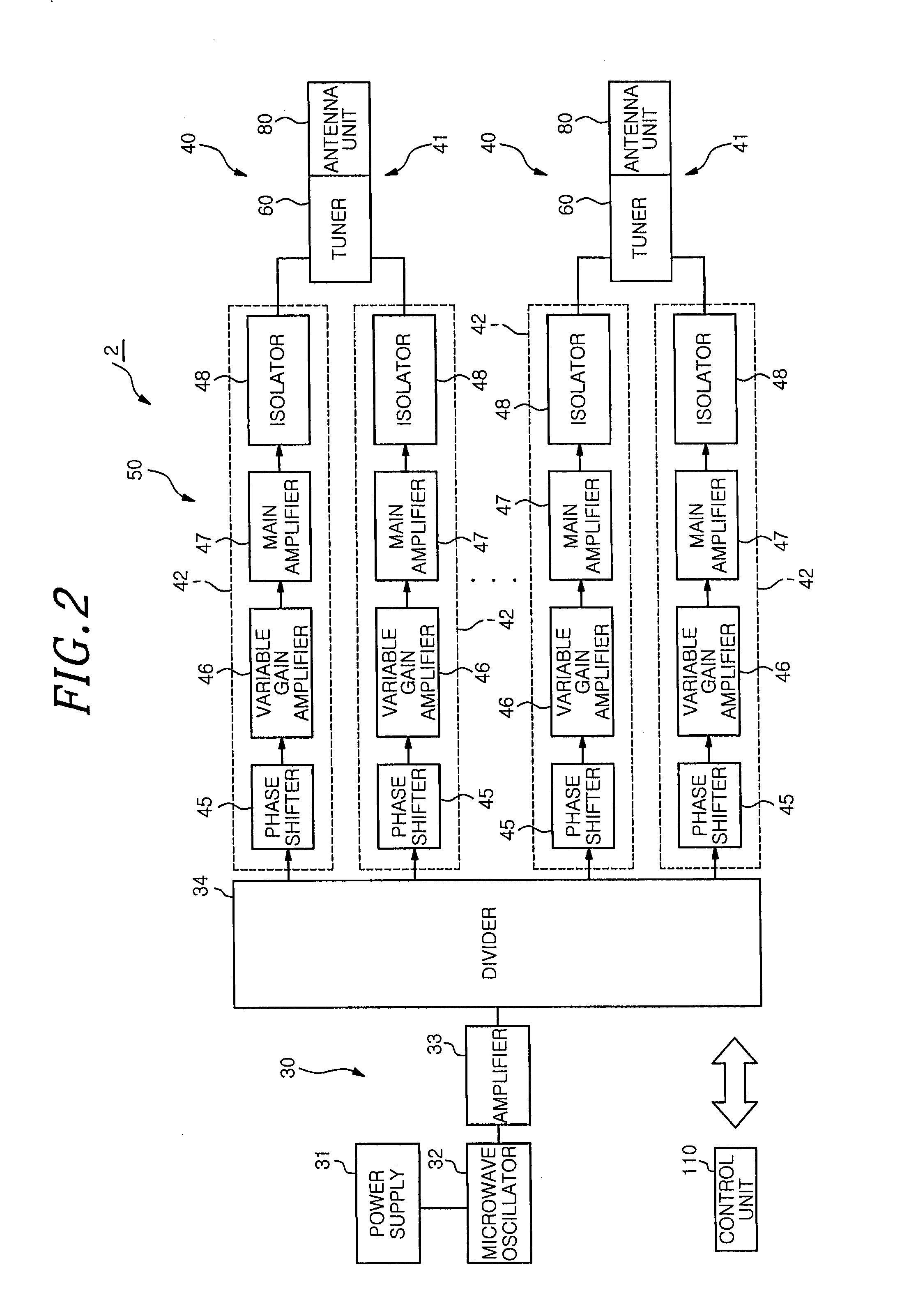
[0032]Hereinafter, embodiments of the present invention will be described in detail with reference to the accompanying drawings. FIG. 1 is a cross-sectional view showing a schematic configuration of a plasma processing apparatus on which a microwave plasma source including a microwave introducing mechanism is mounted in accordance with an embodiment of the present invention. FIG. 2 is a schematic view showing a configuration of the microwave plasma source of FIG. 1.

[0033]A plasma processing apparatus 100 is configured as, e.g., a plasma etching apparatus for performing on a wafer W an etching process as a plasma process. The plasma processing apparatus 100 includes a substantially cylindrical airtight chamber 1 made of a metal such as aluminum, stainless steel, or the like, the chamber 1 being grounded; and a microwave plasma source 2 for forming a microwave plasma within the chamber 1. An opening 1a is formed at an upper portion of the chamber 1, and the microwave plasma source 2 i...


PUM

PropertyMeasurementUnit
frequencyaaaaaaaaaa
frequencyaaaaaaaaaa
frequencyaaaaaaaaaa

Abstract

The microwave introducing mechanism includes an antenna unit having a planar antenna radiating a microwave into a chamber; a tuner for performing impedance matching; and a heat dissipation device for dissipating a heat from the antenna unit. The tuner has a tuner main body including a tubular outer conductor and a tubular inner conductor to serve as a part of a microwave transmission line; slugs provided between the outer conductor and the inner conductor to be movable along a longitudinal direction of the inner conductor; and a driving device for moving the slugs. The heat dissipation device has a heat pipe configured to transfer the heat of the antenna unit from its heat input end to its heat dissipation end.

Description

[0001]This application is a Continuation Application of PCT International Application No. PCT / JP2011 / 069140 filed on Aug. 25, 2011, which designated the United States.FIELD OF THE INVENTION[0002]The present invention relates to a microwave introducing mechanism that introduces a microwave into a chamber in which a plasma process is performed, and a microwave plasma source and a microwave plasma processing apparatus using the same.BACKGROUND OF THE INVENTION[0003]In a manufacturing process of a semiconductor device or a liquid crystal display, a plasma processing apparatus such as a plasma etching apparatus, a plasma CVD film forming apparatus, or the like is used to perform a plasma process such as an etching process, a film forming process, or the like on a target substrate to be processed such as a semiconductor wafer, a glass substrate, or the like.[0004]Recently, for the plasma processing apparatus, some attention has been paid to an RLSA™ microwave plasma processing apparatus c...

Claims


Application Information

Patent Timeline
Patent Type & Authority Applications(United States)
IPC IPC(8): H01J23/00
CPCC23C16/45565C23C16/511H01J37/3222H01J23/005H05H1/46H05H2001/463H01J37/32256H05H1/463H01L21/3065
Inventor IKEDA, TAROOSADA, YUKIKASAI, SHIGERUMIYASHITA, HIROYUKI
Owner TOKYO ELECTRON LTD
Learn More