Illuminating device with LED surface light source covered with optical film

an illumination device and surface light source technology, applied in the direction of fibre light guides, lighting and heating apparatus, instruments, etc., can solve the problems of low efficiency of the light guide panel, low efficiency of the secondary encapsulation efficiency (secondary efficiency for short) of the led as a practical surface light source, and serious source of light pollution, etc., to improve luminance and color rendering properties, simple manufacturing process, and convenient implementation

Inactive Publication Date: 2013-07-18
HANGZHOU FANFEI PHOTOELECTRICITY TECH CO LTD
View PDF0 Cites 35 Cited by
  • Summary
  • Abstract
  • Description
  • Claims
  • Application Information

AI Technical Summary

Benefits of technology

[0058]Beneficial effects: The present invention proposes an LED surface light source device covered with an optical film, that features convenient implementation and great improvement of luminance and color rendering property, simple manufacture process, low cost, high performance / price ratio and with various functions of environmental protection, sterilization, medical healthcare, prevention of static electricity as well as its preparation method.

Problems solved by technology

Direct glare produced by the LED as an illuminator of the point light source is a serious source of light pollution.
Moreover, the secondary encapsulation efficiency (secondary efficiency for short) of the LED as a practical device of the surface light source is still quite low, which is an important cause to the low efficiency of the light guide panel.
However, there still exist such problems as low efficiency of light guide, manufacturing difficulty and high cost.
Although the light guide efficiency can be maximized by optimizing the design of scattering mechanism layer and scattering unit, light will emerge unavoidably from the main surface opposite to the main emergence surface and become ineffective emergent light.
Therefore, the light guide efficiency has a theoretical ceiling and cannot be higher.
: 03101472.0 and Chinese utility model patent 01267387.0, adopts similar principles, and is therefore difficult to break through the ceiling of theoretical efficiency of the light guide.
The surface light source structure revealed by the Chinese invention patent CN100508222C has still such problems as complicated manufacture process, high cost, single functionality and low performance / price ratio and cannot be extensively applied to display, lighting, environmental protection, medical healthcare, backlight source and other technical fields related with LED light source.

Method used


Image

  • Illuminating device with LED surface light source covered with optical film
  • Illuminating device with LED surface light source covered with optical film
  • Illuminating device with LED surface light source covered with optical film

Examples


embodiment 1

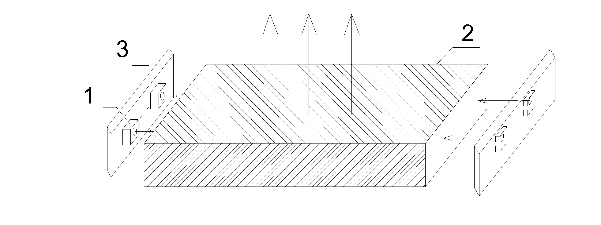
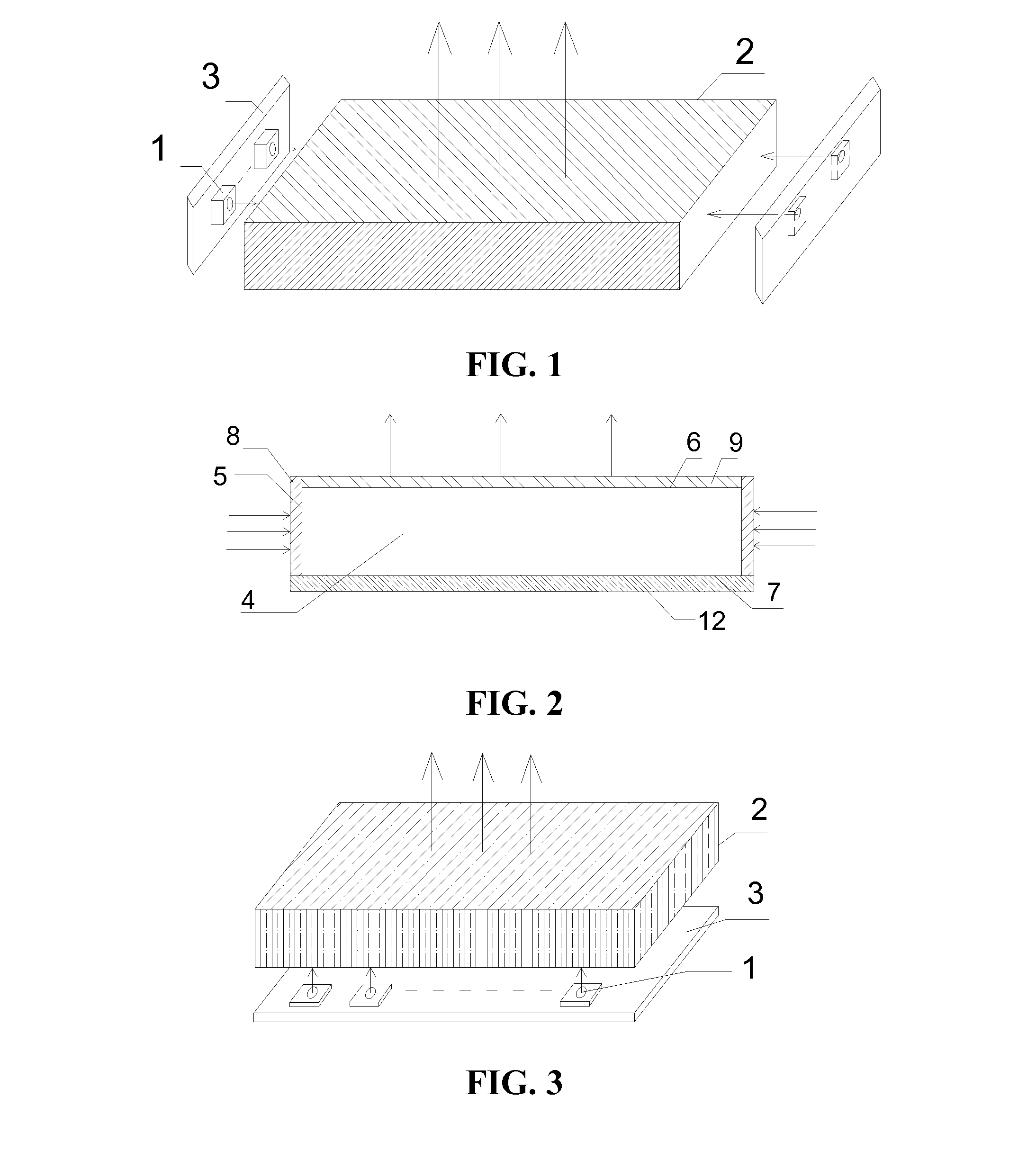
[0095]A glaring-free LED plane light source is provided. As shown in FIG. 1, an LED point light source 1 uses 90 3528SMD LEDs, which are welded to a 165 mm(L)×10 mm(W) aluminum-based printed circuit board. The LEDs are firstly fixed onto a heat sink 3 and then arranged on the incident surface of an illuminator 2. A solid geometry 4 of the illuminator 2 is a PMMA plate with a dimension of 160 mm(L)×65 mm(W)×6 mm(D). The geometry is a solid polygon-hexahedron made of PMMA materials and has totally six surfaces. The LED point light source 1 is arranged on two opposite sides of the hexahedron, and the illuminating side is an incident surface 5. Hence, the figure illustrates two incident surfaces and other two side surfaces are reflection surfaces. One parallel outer surface of the hexahedron is an emergence surface 6 and another parallel outer surface is a reflection surface 7. The illuminator is a side-entry illuminator with light incidence from one side surface and light emergence fro...

embodiment 2

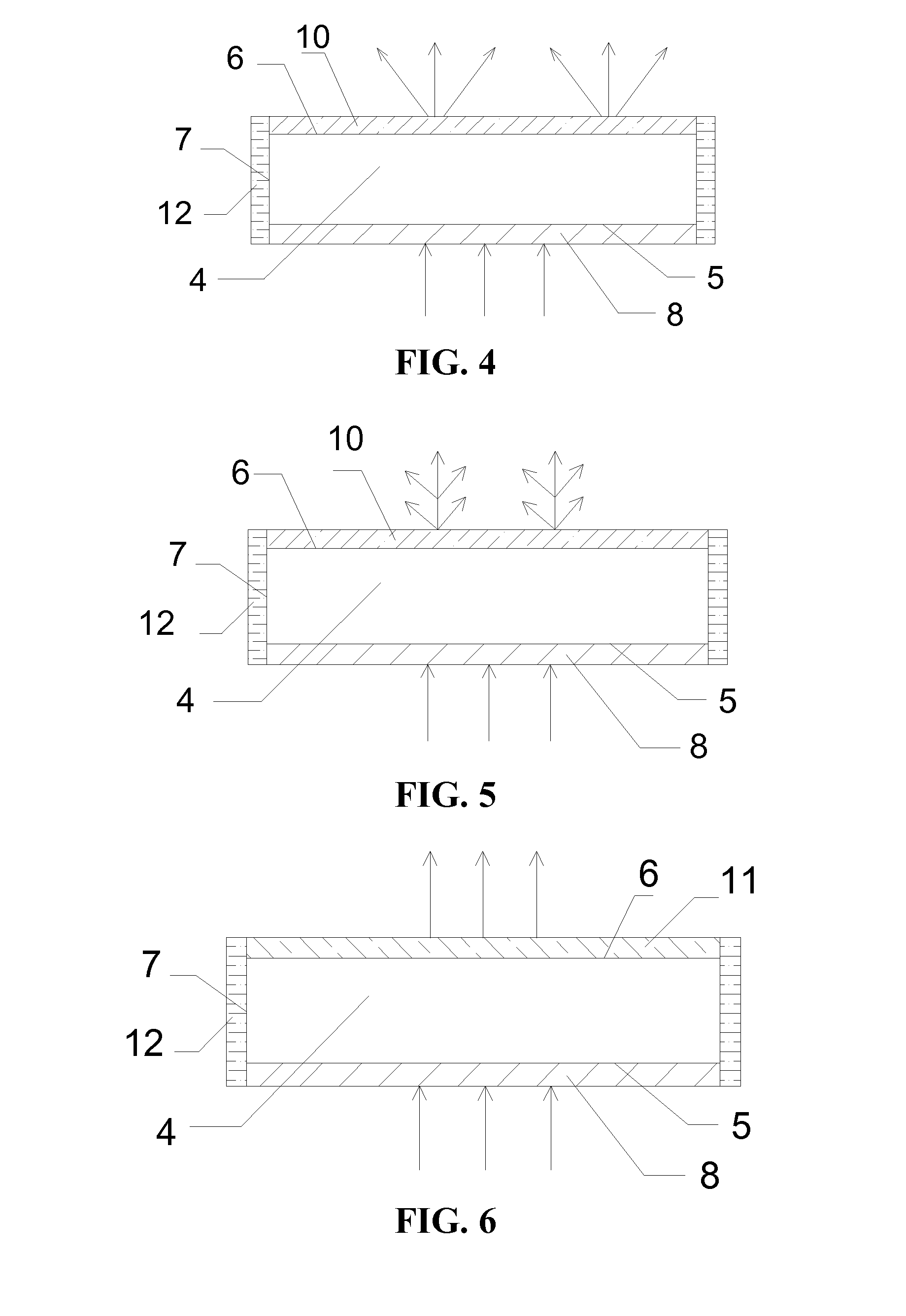
[0099]A multifunctional LED plane light source is provided. As shown in FIG. 3, the solid geometry 4 of the illuminator 2 is made of PMMA plate and its geometry is a solid polyhedron-a hexahedron and has totally six outer surfaces. It is an illuminator made of organic glass plate materials and its geometry is a solid polyhedron-hexahedron and has totally six outer surfaces. The LED point light source 1 illuminator is fixed unto one parallel surface of the hexahedron. This parallel surface is the incident surface 5 and another parallel surface is the emergence surface 6 (other side surfaces are reflection surfaces 7). It is a direct-entry illuminator with light incidence from one parallel surface of the geometry and light emergence from another parallel surface of the geometry. The emergence surface 6 is an emergence surface of a direct-entry illuminator and needs to be covered with a diffusion film 10. As shown in FIG. 4, this embodiment adopts high-purity silicon dioxide powder wit...

embodiment 3

[0104]A tubular LED surface light source is provided. As shown in FIG. 7, the solid geometry of illuminator 2 is made of PMMA tubes and its geometry is a solid rotating body—circular geometry. The outer surface is comprised of two curved surfaces (inner surface and outer surface) and two bottom surfaces. The LED point light source 1 is arranged on one bottom surface of the circular geometry and the bottom surface is the incident surface 5. Therefore, FIG. 7 shows only one incident surface; the other bottom surface is the reflection surface 7 and the inner curved surface of the circular geometry is the reflection surface 7. The outer curved surface of the circular geometry is the emergence surface 6. The illuminator is a side-entry illuminator with light incidence from one bottom surface of the circular geometry and light emergence from the outer curved surface of the circular geometry. As shown in FIG. 8, the reflection surface 7 of this embodiment is covered with the reflection fil...


PUM

PropertyMeasurementUnit
thicknessaaaaaaaaaa
particle sizeaaaaaaaaaa

Abstract

The present invention provides an LED light source, and particularly provides an illuminating device with an LED surface light source covered with an optical film. The device includes: an LED point light source, an illuminator, and a heat sink; wherein the illuminator is an optically transparent solid geometry with an optical film covering the outer surface thereof; wherein at least one outer surface of the solid geometry is an incident surface and at least one outer surface of the solid geometry is an emergence surface; and the optical film is a solid optical medium film; and the LED point light source is fixed on the heat sink, matching with the incident surface of the illuminator.

Description

CROSS-REFERENCE TO RELATED APPLICATIONS[0001]This application is a continuation of International Patent Application No. PCT / CN2011 / 071182, with an international filing date of Feb. 23, 2011, designating the United States, now pending, which is based on Chinese Patent Application No. 201010271534.X, filed Sep. 2, 2010. The contents of these specifications are incorporated herein by reference.BACKGROUND OF THE INVENTION[0002]1. Field of the Invention[0003]The present invention relates to an LED light source, and in particular, to an illuminating device with an LED surface light source covered with an optical film, which is widely applied in the fields related to the LED surface light source such as display, lighting, environmental protection, medical healthcare, backlight source.[0004]2. Description of the Related Art[0005]Direct glare produced by the LED as an illuminator of the point light source is a serious source of light pollution. To overcome direct glare produced by the point ...

Claims


Application Information

Patent Timeline
Patent Type & Authority Applications(United States)
IPC IPC(8): H01L33/58
CPCG02B6/001G02B6/0051F21V7/22F21V2200/20H01L33/58G02B5/0242G02B6/0085F21Y2101/02F21Y2115/10F21V7/28
Inventor WU, MINGFAN
Owner HANGZHOU FANFEI PHOTOELECTRICITY TECH CO LTD
Why Eureka
Try Eureka