Stator for electric rotating machine

a technology of electric rotating machines and stator coils, which is applied in the direction of windings, cooling/ventilation arrangements, dynamo-electric components, etc., can solve the problems of difficult effective the ineffective cooling of the turn portions of the small electric conductor segments, so as to reduce the resistance of the stator coil, increase the flow rate of cooling air, and effectively cool the

Active Publication Date: 2013-07-18
DENSO CORP
View PDF3 Cites 2 Cited by
  • Summary
  • Abstract
  • Description
  • Claims
  • Application Information

AI Technical Summary

Benefits of technology

[0010]With the above arrangement, when the cooling air passes by the first turn portion, the apex part of the first turn portion can serve as a guide vane to guide the flow of the cooling air, thereby lowering the resistance of the stator coil to the flow of the cooling air and thus increasing the flow rate of the cooling air. Moreover, the apex part of the second turn portion can be more reliably exposed to the cooling air, thereby being more effectively cooled by the cooling air.
[0011]It is preferable that each of the first to the fourth in-slot portions has a substantially rectangular cross section. In this case, it is possible to maximize the space factors of the stator coil in the slots of the stator core and minimize the electrical resistance of the stator coil. Consequently, it is possible to lower the temperature of the entire stator coil.
[0012]The stator coil may be comprised of a plurality of substantially U-shaped electric conductor segments that are mounted on the stator core and electrically connected to one another. In this ease, it is possible to easily realize the above-described arrangement of the first and second turn portions of the stator coil.

Problems solved by technology

With the above structure, however, it may be difficult to effectively cool the turn portions of the small electric conductor segments.
As a result, the turn portions of the small electric conductor segments may not be effectively cooled by the cooling air.

Method used


Image

  • Stator for electric rotating machine
  • Stator for electric rotating machine
  • Stator for electric rotating machine

Examples


Embodiment Construction

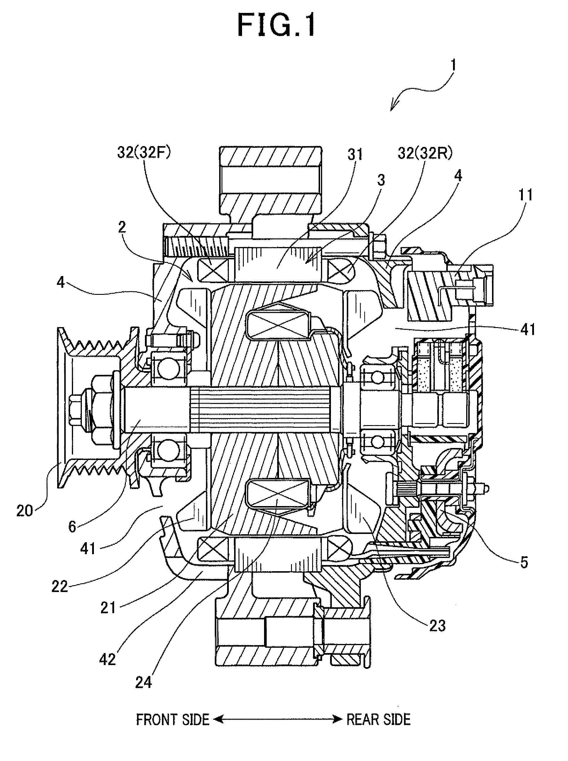
[0022]FIG. 1 shows the overall configuration of an automotive alternator 1 according to an exemplary embodiment. The alternator 1 is designed to be used in a motor vehicle, such as a passenger car or a truck.

[0023]As shown in FIG. 1, the alternator 1 includes a rotor 2, a stator 3, a frame 4, a rectifier 5, a voltage regulator 11 and a pulley 20.

[0024]The rotor 2 includes a rotating shaft 6, a pair of Lundell-type magnetic pole cores 21 and a field coil 24. The rotating shaft 6 is rotatably supported by the frame 4. The rotating shaft 6 has the pulley 20 mounted on a front end portion (i.e., a left end portion in FIG. 1) thereof, so that it can be driven by an internal combustion engine (not shown) of the vehicle via the pulley 20. Each of the magnetic pole cores 21 has a plurality of magnetic pole claws. The field coil 24 is made of, for example, an insulation-treated copper wire and wound into a hollow cylindrical shape. The magnetic pole cores 21 are fixed on the rotating shaft 6...


PUM


Abstract

A stator coil includes first to fourth in-slot portions and first and second turn portions. Both the first and third in-slot portions are received in one slot of a stator core, while both the second and fourth in-slot portions are received in another slot. The first and second turn portions both protrude from an axial end face of the stator core and respectively connect the pair of the first and second in-slot portions and the pair of the third and fourth in-slot portions. The second turn portion is located inside the first turn portion. When viewed along an axial direction of the stator core, the first and second turn portions extend so as to cross each other with a reference line C interposed therebetween; the reference line C is defined to extend along a circumferential direction of the stator core through an intersection between the first and second turn portions.

Description

CROSS-REFERENCE TO RELATED APPLICATION[0001]This application is based on and claims priority from Japanese Patent Application No. 2012-7761, filed on Jan. 18, 2012, the content of which is hereby incorporated by reference in its entirety into this application.BACKGROUND[0002]1. Technical Field[0003]The present invention relates to stators for electric rotating machines that are used in, for example, motor vehicles as electric motors and electric generators.[0004]2. Description of Related Art[0005]There is disclosed, for example in Japanese Unexamined Patent Application Publication No. H11-164504, a stator for an electric rotating machine which includes a stator coil formed by joining corresponding pairs of ends of electric conductor segments. The stator coil has a double annular structure. More specifically, the electric conductor segments forming the stator coil are comprised of a plurality of pairs of large and small U-shaped electric conductor segments. For each electric conducto...

Claims


Application Information

Patent Timeline
Patent Type & Authority Applications(United States)
IPC IPC(8): H02K3/24H02K3/28
CPCH02K3/12H02K3/28H02K3/24
Inventor OKAMURA, TOMOYUKIKAMEGAWA, NORIO
Owner DENSO CORP
Why Eureka
Try Eureka