Methods and devices for intra-atrial shunts having selectable flow rates

a technology of shunt and flow rate, applied in the field of heart failure treatment, can solve the problems of increased pulmonary venous pressure, shortness of breath, exercise intolerance, etc., and achieve the effects of reducing both left atrial and pulmonary venous pressure, reducing the risk of acute worsening of heart failure, and reducing the risk of later development of pulmonary hypertrophy

Active Publication Date: 2013-07-18
CORVIA MEDICAL
View PDF5 Cites 52 Cited by
  • Summary
  • Abstract
  • Description
  • Claims
  • Application Information

AI Technical Summary

Benefits of technology

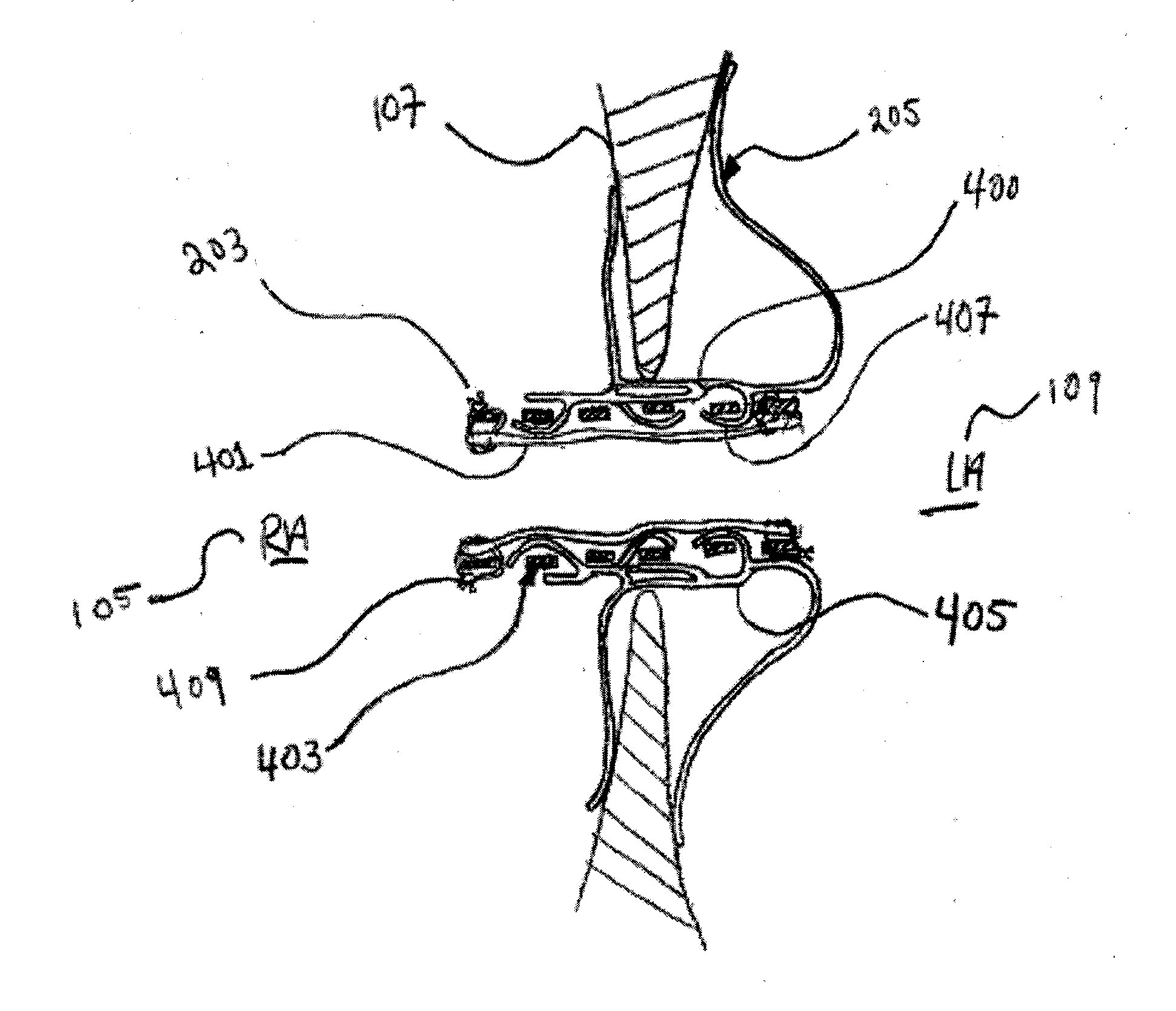
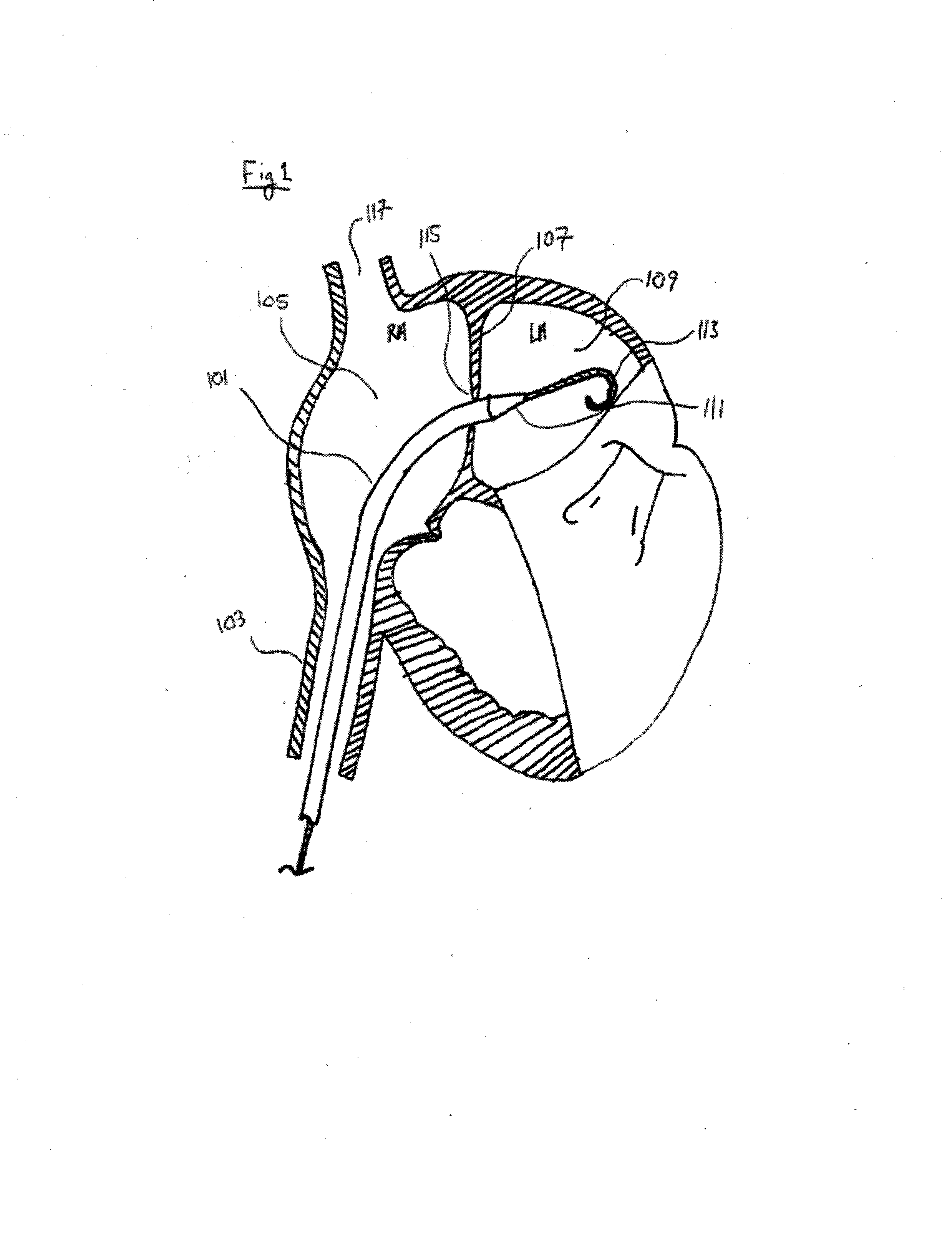
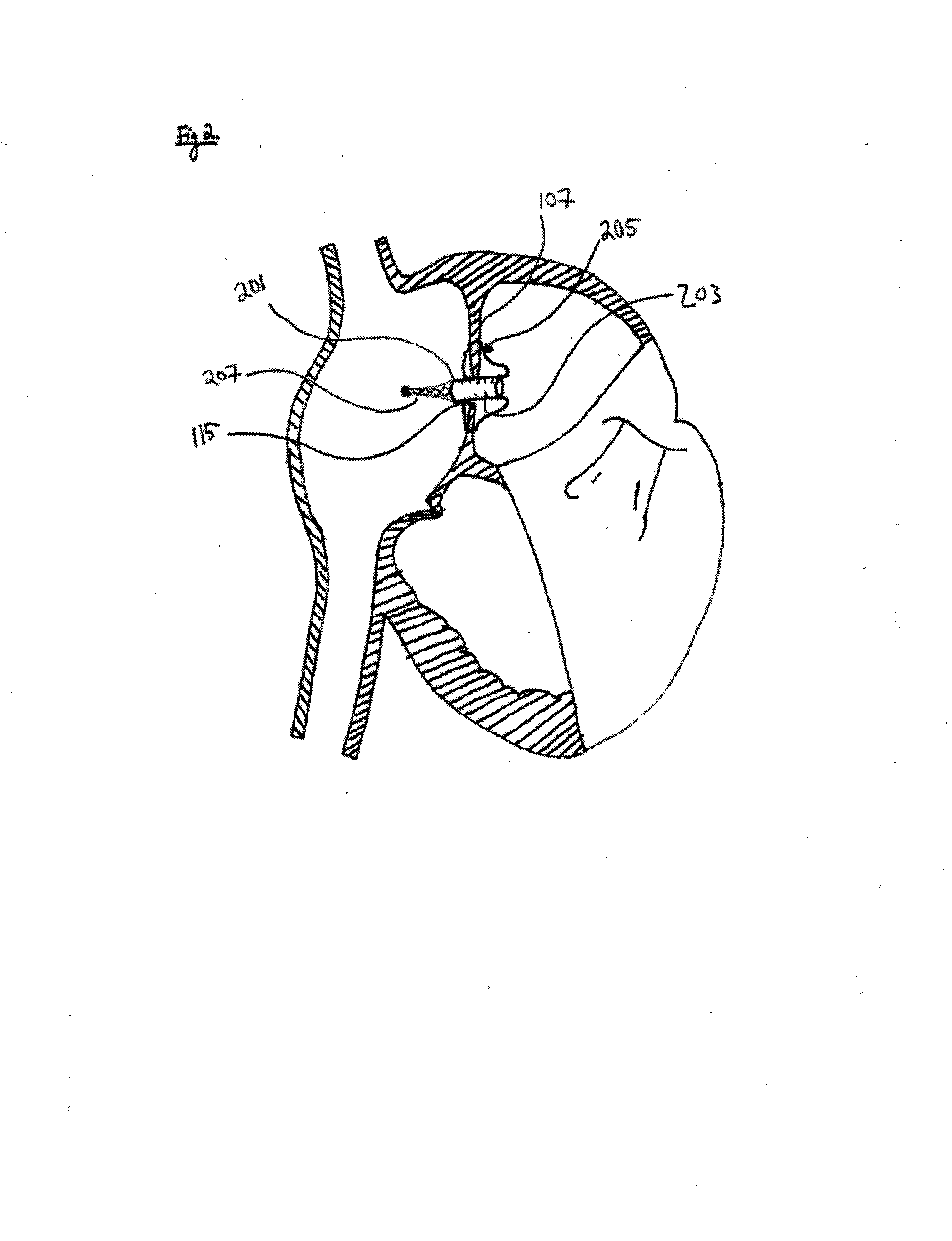
[0009]In general, the present invention concerns treating heart disease by reducing both left atrial and pulmonary venous pressure. To this end, devices and methods are disclosed herein which may include the creation of a pressure relief shunt in the atrial septum or the placing of a device having a changeable hydraulic diameter into an already existing aperture in the atrial septum. Furthermore, devices and methods are disclosed herein which allow for adjusting the pressure relief shunt in response to the natural progression of the patient during the course of treatment. Additionally, devices and methods are disclosed which provide a treatment which may be adjusted to or which automatically adjusts to the changing conditions in the body as a result of the creation of the pressure relief shunt or the presence of the extant atrial septal aperture. Furthermore, devices and methods are disclosed herein which mitigate the risk of acute worsening of heart failure following the creation of a pressure relief shunt or of an extant atrial septal aperture by allowing for gradual increase in the hydraulic diameter of an implanted device after implantation. Devices and methods are disclosed herein which significantly mitigate the risk of later development of pulmonary hypertrophy by implanting a device which gradually decreases hydraulic diameter in size over time or in response to the natural hemodynamic changes in the heart.
[0015]In some embodiments, the inventive device including a tubular body and a number of anchoring members is disclosed, where the tubular body may be configured such that its first diameter initially allows only a small volume of blood to shunt from the left atrium to the right atrium. The tubular body may then be designed to gradually expand over the course of days, weeks, or months, to subsequent diameters that allow a larger volume of blood to pass through the shunt. The shunt may be configured so that the internal portion or orifice will expand to a predetermined final subsequent diameter in order to allow a therapeutic amount of blood flow through the shunt. In such embodiments, the orifice of the inventive device may be configured to expand slowly so that the risk of acute worsening of heart failure that may be caused by a sudden hemodynamic change is substantially reduced.
[0016]In some embodiments, the inventive device includes a tubular body and a number of anchoring members and is configured to open to an internal diameter that allows sufficient blood to flow through the shunt in order to reduce the left atrial and pulmonary venous pressure. The tubular body may be configured such that over time the internal diameter of the shunt gradually contracts. The internal diameter of the inventive device may be designed to shrink to a predetermined final diameter. The predetermined final diameter may be sized to allow some clinically relevant blood flow through the shunt while simultaneously eliminating the risk of developing hypertrophic pulmonary arteries. Alternatively, the inventive device may be configured such that given enough time the internal diameter becomes completely occluded and blood flow through the shunt is prevented.

Problems solved by technology

Left heart failure can lead to elevated pulmonary venous pressure, which may cause respiratory problems, including shortness of breath and exercise intolerance.
The adverse clinical result of each of these conditions is similar; the heart failure leads to elevated pressure in the left atrium and elevated pressure in the pulmonary veins, impeding proper flow of oxygenated blood through the blood supply.
More generally, diastolic heart failure is failure of the ventricle to adequately relax and expand in order to fill with blood, causing a decrease in the stroke volume of the heart.
Presently, there exist very few treatment options for patients suffering from diastolic heart failure.
The hypertrophy of the pulmonary arteries in turn leads to worsening symptoms of heart failure.
The hemodynamic conditions associated with diastolic heart failure are not static, and attempting to treat the disease with a static pressure relief shunt represents a deficiency in the prior art.
For example, if a shunt is sized too large the short term effect of the creation of a pressure relief shunt may include a sudden worsening of heart failure.
Furthermore, if the pressure relief shunt is sized too small the patient may not experience any clinical improvement from the procedure.
The size of the pressure relief shunt required for efficacious treatment of diastolic heart failure may be difficult to predetermine, and varies with the condition of the patient and with the state of the underlying disease.
This treatment method and apparatus suffers from deficiencies.
For example, the requirement to leave a balloon in place in order to gradually open the pressure relief shunt can create significant problems such as the problem of keeping the balloon in place despite the significant pressure differential across the shunt.
Furthermore, the requirement to leave a catheter dwelling within the circulation carries significant potential risks, including increased risk of pulmonary embolism, sepsis, sensitization or allergic reaction, and other potentially adverse clinical reactions.
The constantly evolving nature of heart failure represents a significant challenge for the treatment methods currently disclosed in the prior art.

Method used


Image

  • Methods and devices for intra-atrial shunts having selectable flow rates
  • Methods and devices for intra-atrial shunts having selectable flow rates
  • Methods and devices for intra-atrial shunts having selectable flow rates

Examples


Embodiment Construction

[0050]Certain specific details are set forth in the following description and Figs. to provide an understanding of various embodiments. Those of ordinary skill in the relevant art will understand that they can practice other embodiments without one or more of the details described below. Further, while various processes are described herein with reference to steps and sequences, the steps and sequences of steps are not be understood as being required to practice all embodiments of the present invention.

[0051]Unless otherwise defined, explicitly or implicitly by usage herein, all technical and scientific terms used herein have the same meaning as those which are commonly understood by one of ordinary skill in the art to which this present invention pertains. Methods and materials similar or equivalent to those described herein may be used in the practice or testing of the present invention. In case of conflict between a common meaning and a definition presented in this document, latt...


PUM


Abstract

Devices and methods for treating heart disease by normalizing elevated blood pressure in the left and right atria of a heart of a mammal are disclosed. The devices are adapted to permit fluid flow across the membrane in which the device is implanted at first rate, and at a second rate, wherein a difference between the first rate and the second rate is not solely dependent upon variations in blood pressure differential across the membrane due to the heart's pumping cycle.

Description

CROSS-REFERENCE TO RELATED APPLICATIONS[0001]This application is a non-provisional of U.S. Provisional Application No. 61 / 579,426, filed Dec. 22, 2011, entitled “Systems, Methods and Devices for Resizing Intra-Atrial Shunts” and of U.S. Provisional Application No. 61 / 659,520, filed Jun. 14, 2012, entitled “Adjustable Intra-Atrial Shunts”, both of which are incorporated by reference herein in their entireties.FIELD OF THE INVENTION[0002]The present invention relates to methods and devices for treating heart failure. In particular, the present invention relates to methods and devices for treating heart failure by reducing elevated blood pressure in a heart chamber by creating a pressure relief shunt. Additionally, the present invention relates to methods and devices for customizing, adjusting or manipulating the flow of blood through the shunt in order to enhance the therapeutic effect of the pressure relief shunt.BACKGROUND[0003]Heart failure is a condition effecting millions of peop...

Claims


Application Information

Patent Timeline
Patent Type & Authority Applications(United States)
IPC IPC(8): A61M27/00
CPCA61M27/002A61F2/2412A61F2/2418A61F2/24A61B2017/00623A61F2/2493A61B2017/00592A61B2017/00584A61B2017/00575A61B2017/00247A61B2017/00606
Inventor MCNAMARA, EDWARDSUTHERLAND, MICHAEL W.FINCH, MATTHEW J.FORCUCCI, STEPHEN J.MITZEL, JOHN
Owner CORVIA MEDICAL
Why Eureka
Try Eureka