
Resource optimization using environmental and condition-based monitoring

a technology of condition-based monitoring and resource optimization, applied in adaptive control, reradiation, instruments, etc., can solve the problems of increasing the cost of energy (coe), increasing the cost of maintenance and repair, and increasing the susceptibility to damaging wind conditions. , to achieve the effect of quick simulation

Inactive Publication Date: 2013-07-18
MICHIGAN AEROSPACE
View PDF20 Cites 56 Cited by
  • Summary
  • Abstract
  • Description
  • Claims
  • Application Information

AI Technical Summary

Benefits of technology

The patent text describes a system for monitoring and controlling wind turbines to prevent damage and improve efficiency. The system combines advanced sensors, decision making tools, and control strategies to actively manage individual turbines and wind farms. The system can also be used for smart buildings, allowing users to model and optimize energy consumption. The technical effects of the invention include improved condition monitoring, load mitigation, and reduced maintenance costs, resulting in lower energy costs and increased power output.

Problems solved by technology

As wind turbine rotor diameters increase in size, especially for offshore wind farms, susceptibility to damaging wind conditions is also increasing.
The extreme and fatigue loads that a turbine must endure increase the Cost of Energy (CoE) significantly through higher maintenance and repair costs, reduced availability, shorter lifetimes and increased initial purchase cost due to the need for greater design margin.
These problems are exacerbated for larger turbines and when major repairs require cranes to replace damaged components.
While success has been achieved in monitoring isolated turbine elements, the community has made few attempts to develop a comprehensive picture of the wind energy problem across all its important scales.

Method used


Image

  • Resource optimization using environmental and condition-based monitoring
  • Resource optimization using environmental and condition-based monitoring
  • Resource optimization using environmental and condition-based monitoring

Examples


Embodiment Construction

Optimal Reasoning and Decision Making

[0045]For concreteness, we describe the reasoning algorithms in the context of the CM technology of the present invention, but as emphasized in later sections, the reasoning and decision making algorithms are generic and may be used to solve problems in domains beyond that of wind energy.

Condition Monitoring

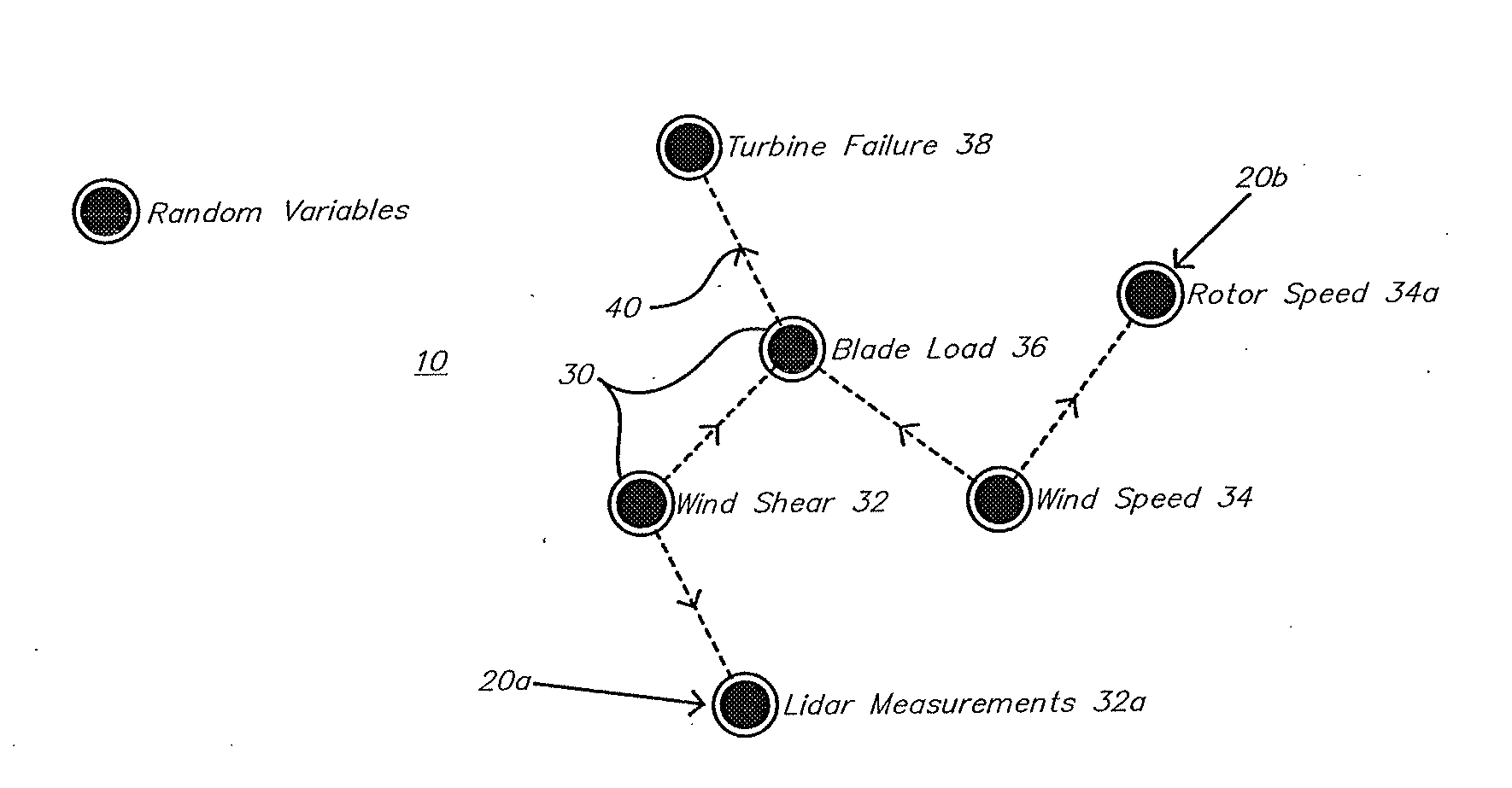
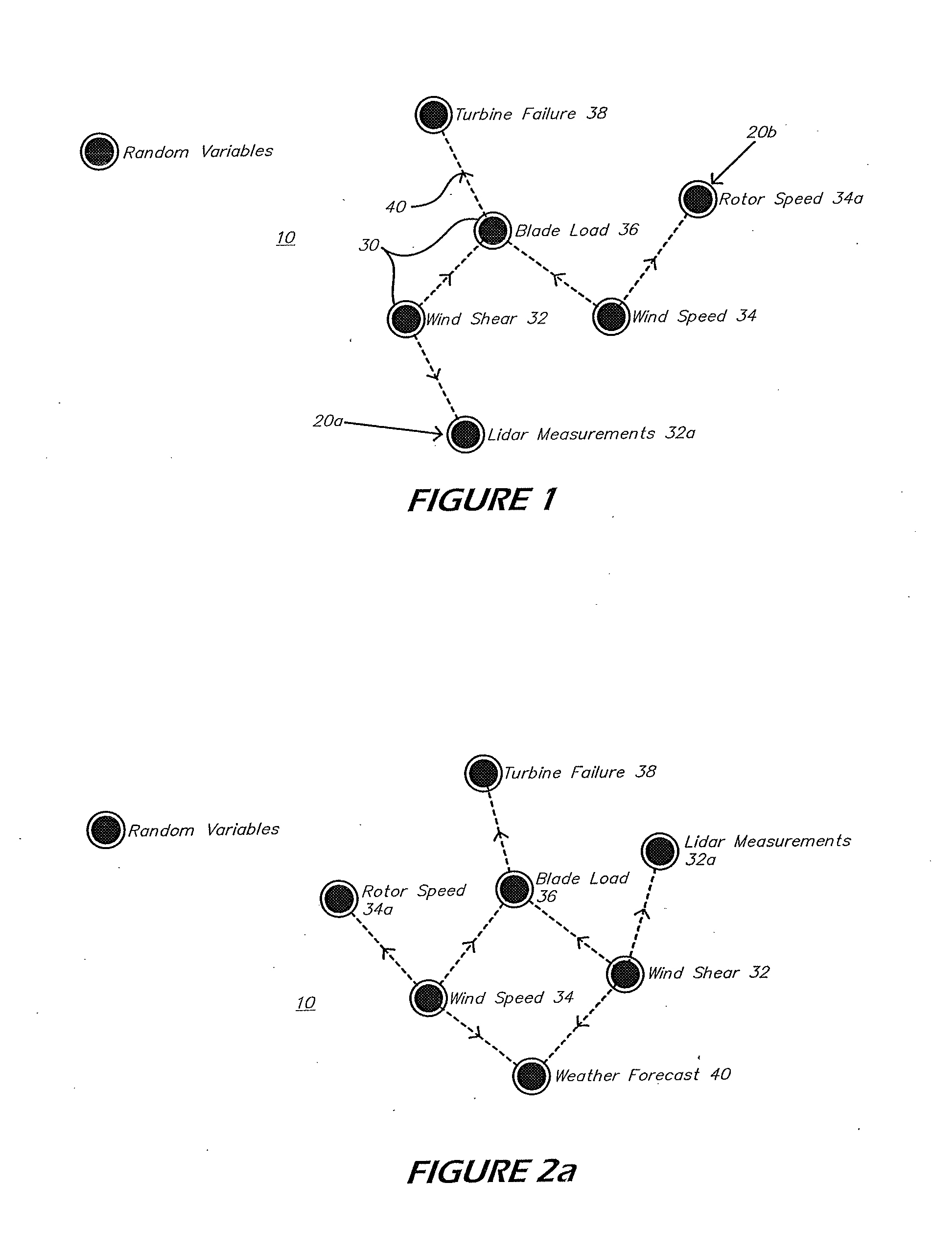
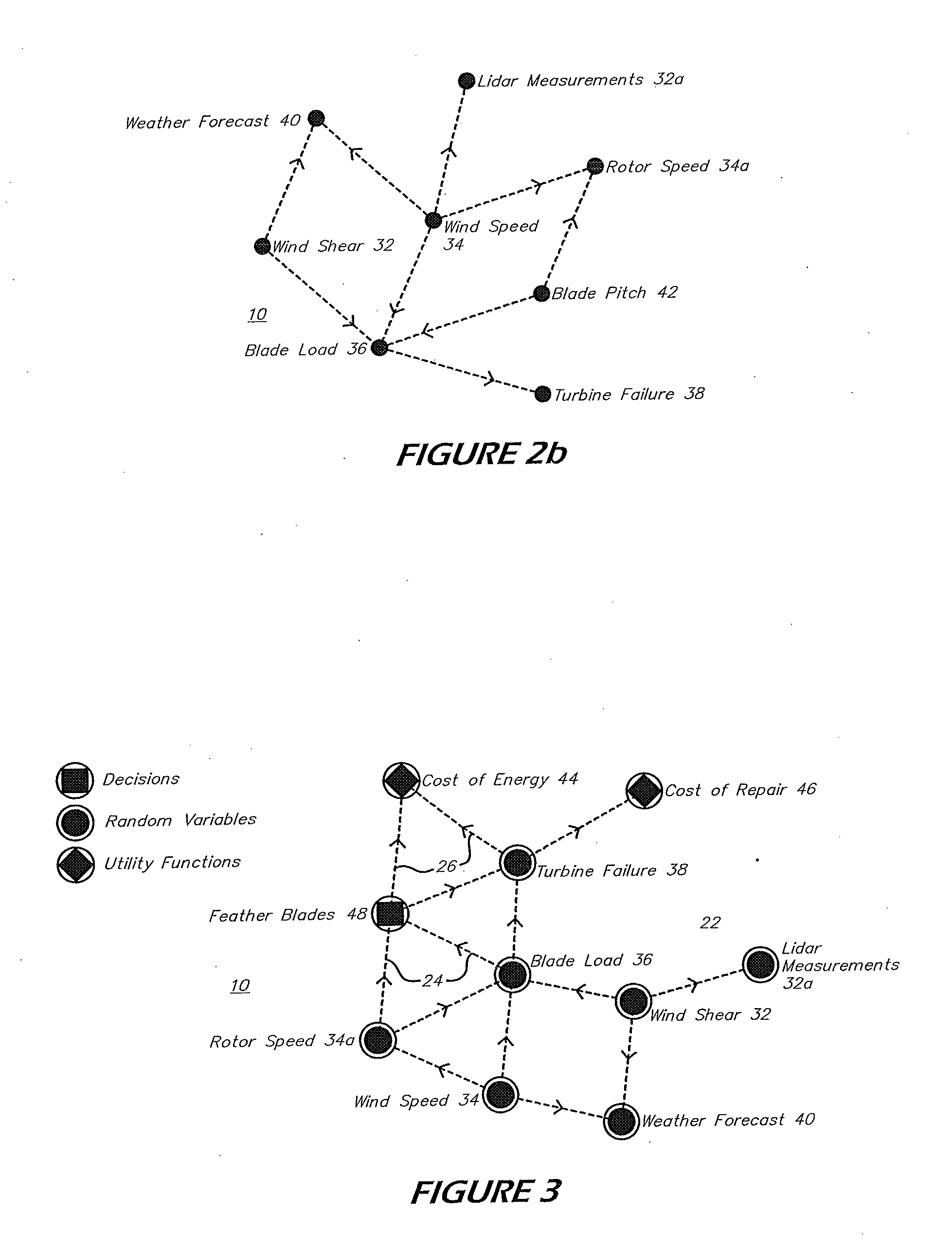
[0046]At its core, the CM technology of the present invention builds a probabilistic model of the wind energy system, from the level of individual turbine components up to the structure of the atmosphere—at whatever level of resolution is desired, and using whatever data sources are available. This model can then be interrogated to predict, for example, the expected power output of a wind turbine as a function of time, or the likelihood of a given component failing within the next two weeks.

[0047]Because the notions of decision making and utility functions may be directly integrated into CM models according to the present invention, however, w...


PUM


Abstract

In a method for dynamically optimizing resource utilization in a system over time according to one or more objectives, data including information indicative of current environmental conditions, upcoming environmental conditions, a current state of a system configuration, and current system operating conditions is dynamically updated. Automatic analysis of the data using a probabilistic model based on conditional relationships is performed periodically. For each periodically generated set of possible system control actions, a probabilistic model is used to automatically analyze each possible system control action and an optimal system control action is selected based on a set of current utility functions. For each periodically generated set of possible system control actions, control of the system according to the optimal system control action selected from the possible system control actions. Resource optimization couples condition-based and environmental monitoring with automated reasoning and decision making technologies, to develop real time optimal control and decision strategies.

Description

[0001]This application claims priority to U.S. Provisional Application No. 61 / 583,976 filed on Jan. 6, 2012, which is hereby incorporated by reference.I. BACKGROUND OF THE INVENTIONField of the Invention[0002]The present invention relates to a system and method for integrating condition monitoring, sensor, and system configuration information to optimize resources over time according to one or more objectives.RESOURCE OPTIMIZATION[0003]The goal of resource optimization is to make use of limited resources to optimize one or more objectives. In a sense, the problem may be regarded as a one of optimal decision making in the presence of uncertainty. When provided data, constraints, and objectives, resource optimization seeks to make decisions that optimize the stated objectives.[0004]Consider as an example the problem of wind energy. The goal of the wind energy industry is to generate electrical power from captured wind energy. The limited resource is the wind itself, and one wishes to ...

Claims


Application Information

Patent Timeline
Patent Type & Authority Applications(United States)
IPC IPC(8): G05B13/04F03D7/00
CPCG05B13/042F03D7/00G01S17/95Y02E10/723G01S17/58F03D7/045Y02A90/10Y02E10/72
Inventor TCHORYK, JR., PETERLEWIS, MATTHEW J.RICHEY, CHARLES J.JOHNSON, DAVID K.ZUK, DAVID M.
Owner MICHIGAN AEROSPACE
Learn More