Luminescent converter

a technology of converters and mscs, applied in the field ofluminescent converters, can solve the problems of limited number of discrete sizes of mscs that are stable, and achieve the effect of improving efficiency and cos

Inactive Publication Date: 2013-08-01
KONINKLJIJKE PHILIPS NV
View PDF3 Cites 2 Cited by
  • Summary
  • Abstract
  • Description
  • Claims
  • Application Information

AI Technical Summary

Benefits of technology

[0003]Based on this background, it was the object of the present invention to provide means for converting light energy, particularly of sunlight, with improved characteristics in terms of efficiency and cost.
[0006]The use of MSCs as a luminescent material turns out to be favorable for various reasons. The absorption and reemission spectra of the MSCs can for instance be chosen such that a large part of the solar spectrum is absorbed, and that it is reemitted at a wavelength that matches very well the characteristics of solar cells, making the luminescent converter suited for a use in a luminescent solar concentrator (LSC). Moreover, the overlap between absorption and emission spectra can be made small, minimizing losses due to reabsorption of photons. Furthermore, MSCs often have a high quantum efficiency, which improves the performance of the luminescent converter.
[0008]Moreover, the MSCs are preferably symmetric crystallites. In this way the number of surface atoms is minimized, yielding a thermodynamically stable composition and with a very low concentration of lattice defects that might quench the luminescence.
[0010]The MSCs may be composed of a single homogeneous material. In a preferred embodiment, the MSCs are covered with a coating. In this way the favorable characteristics of the MSCs can be supplemented with additional positive features depending on the type of coating used. The coating may for example comprise an organic material and / or an inorganic semiconductor like PbS. The coating may for instance passivate the surface of an MSC, thus protecting it and increasing the lifetime of the luminescent converter.
[0014]In another preferred embodiment of the invention, the concentration of the MSCs varies spatially within the luminescent converter. In this way the absorption and emission characteristics can optimally be adapted to the geometrical design of the converter. It is preferred in this respect that the concentration of the MSCs has lower values near at least one border of the luminescent converter, particularly a border through which light is emitted.
[0017]Furthermore, the luminescent converter may optionally comprise a mirror on at least one of its surfaces in order to prevent light from being emitted in unwanted directions.

Problems solved by technology

Therefore, there is only a limited number of discrete sizes of MSCs that are stable.

Method used


Image

  • Luminescent converter
  • Luminescent converter
  • Luminescent converter

Examples


Embodiment Construction

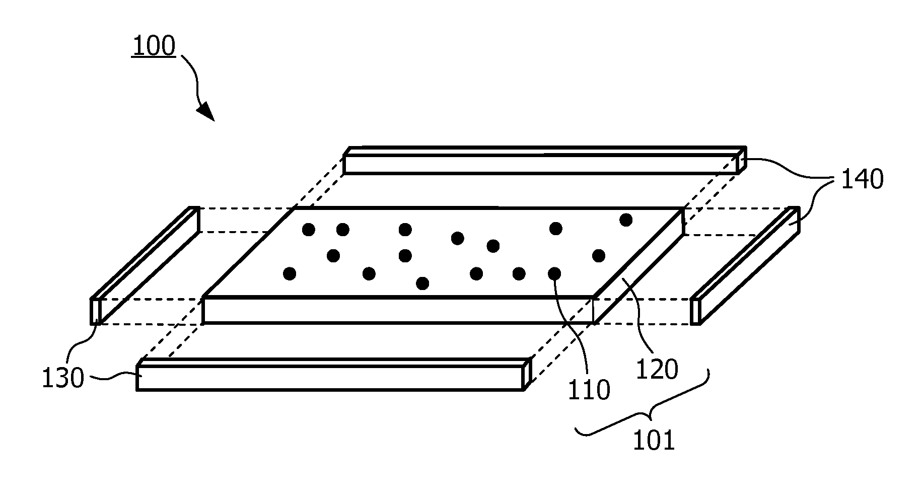
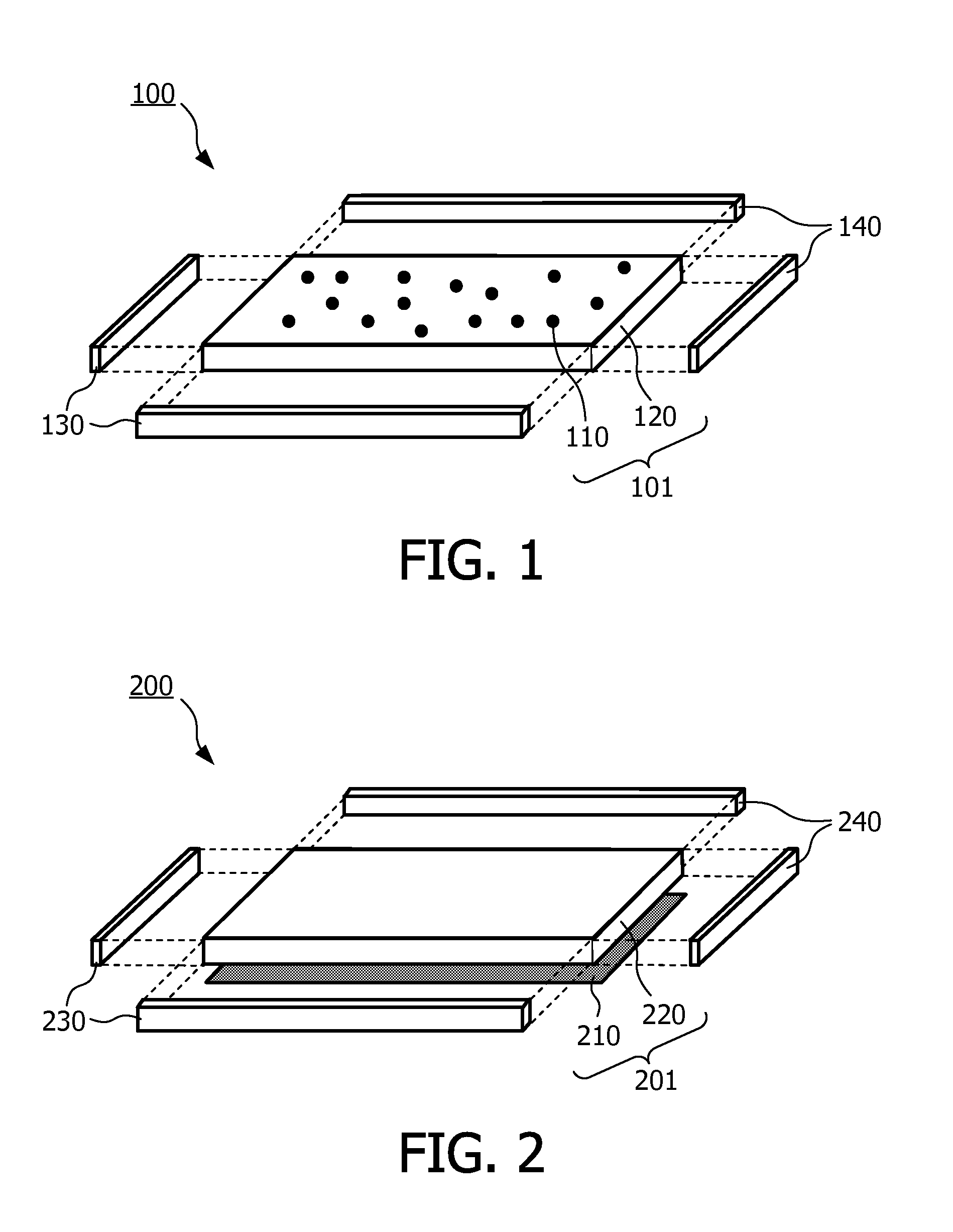
[0025]The present invention will in the following primarily be described with respect to a particular application, i.e. as a “luminescent solar concentrator” LSC. The concept of the LSC is based on a transparent (polymer or glass) plate containing fluorescent dyes. Solar radiation is absorbed by the dyes and reemitted in all directions. Due to internal reflection within the polymer or glass matrix, most of the reemitted light is guided to the sides of the plate, where solar cells can be attached. A small effective area of solar cells is thus required for a relatively large area that collects the sun, making the device economically favorable.

[0026]However, the overall efficiency of state-of-the-art LSCs is still not sufficient to compete with conventional solar cells (Currie, Science 321 (2008) 226). This is due to loss mechanisms, which are caused by

[0027](1) light that is not absorbed by the plate;

[0028](2) light that is reemitted within the escape cone, thereby leaving the plate;

[...


PUM


Abstract

The invention relates to a luminescent converter (101) that may for example be used as a luminescent solar concentrator (LSC) in a solar power generator (100). The luminescent converter (101) comprises magic-sized clusters (110), MSCs, of a luminescent material. Preferably, said luminescent material comprises a compound of two elements from groups IV and VI, for example PbSe. The MSCs (110) may be embedded in a transparent light guiding element (120) or be embedded in a thin film on a surface thereof.

Description

FIELD OF THE INVENTION[0001]The invention relates to a luminescent converter for converting parts of the spectrum of incident light to larger wavelengths. Moreover, it relates to a method of manufacturing such a luminescent converter and to a solar power generator comprising such a luminescent converter.BACKGROUND OF THE INVENTION[0002]US 2009 / 0010608 A1 discloses a luminescent solar concentrator (LSC) that is used to absorb a certain part of the spectrum of sunlight, wherein the absorbed energy is reemitted at a larger wavelength, which matches the absorption characteristics of an associated solar cell. In a particular embodiment, the LSC may comprise quantum dots of PbSe as a luminescent material.SUMMARY OF THE INVENTION[0003]Based on this background, it was the object of the present invention to provide means for converting light energy, particularly of sunlight, with improved characteristics in terms of efficiency and cost.[0004]This object is achieved by a luminescent converter...

Claims


Application Information

Patent Timeline
Patent Type & Authority Applications(United States)
IPC IPC(8): H01L31/0232H01L31/18
CPCC09K11/02C09K11/08H01L31/055H01L31/0547H01L31/02322H01L31/18Y02E10/52
Inventor KOOLE, ROELOFHOUTEPEN, ARJAN JEROENRONDA, CORNELIS REINDER
Owner KONINKLJIJKE PHILIPS NV
Why Eureka
Try Eureka