Ophthalmic lens assembly having an integrated antenna structure

Active Publication Date: 2013-08-01
JOHNSON & JOHNSON VISION CARE INC
View PDF5 Cites 181 Cited by
  • Summary
  • Abstract
  • Description
  • Claims
  • Application Information

AI Technical Summary

Benefits of technology

[0013]In accordance with the present invention, an antenna or antenna assembly may be incorporated into mechanical devices such as ophthalmic devices, including lenses and contact lenses. While exemplary embodiments will be described with respect to contact lenses (wearable) or implantable lenses (IOLs), it is important to note that the present invention may be utilized in any number of related or non-related devices. Wearable or contact lenses may incorporate a lens assembly having electronically adjustable focus to augment the performance of the eye and/or it may incorporate electronic sensors to detect concentrations of particular chemicals in the tear film. The use of such embedded electronics in a lens assembly potentially introduces the need for one and/or two way communication, and for a method of powering the electronics or recharging a power storage device. The antenna/antenna assembly of the present invention may be utilized to transmit and/or receive information and/or data as well as provide a means for charging the battery, batteries or capacitors utilized to power the electronics by inductive charging or radio frequency (RF) energy harvesting methods. As known in the relevant art, RF energy harvesting systems may be implemented where circuit operation is similar to inductive charging, but at higher frequencies, for example, 900 megahertz to 2.4 gigahertz. In the art, “inductive charging” is often associated with low frequency, for example, 125 kilohertz or 13.5 megahertz, near field coupling to a coil-like structure and RF energy harvesting is associated with longer distance, lower power, higher frequency waves coupled to an RF antenna.
[0014]An exemplary optical lens assembly in accordance with the present invention may comprise a circuit board or substrate, an electronic circuit, a lens structure (optics) and an antenna structure. The electronic circuit may comprise a number of electronic components mounted on the circuit board and the circuit board may provide wiring traces to interconnect the electronic components. The circuit board may be mechanically attached to the lens to form a rigid component of the optical lens assembly. Alternately, the circuit board may not be mechanically attached to the lens and thus not form a rigid component of the optical lens assembly. This arrangement may vary depending on the type of lens. In some exemplary embodiments, the antenna structure or antenna may include a coil comprising one or more loops of wire mounted around and concentric with the lens structure. In alternate exemplary embodiments, the antenna may comprise one or more wiring traces on the circuit board. The antenna

Problems solved by technology

As electronic devices continue to be miniaturized, it is becoming increasingly more likely to create wearable or embeddable microelectronic devices for a variety of uses.
Embedding electronics and communication capability in a contact lens presents general challenges in a number of areas, including the limited size of the components, in particular the thickness as well as the maximum length and width, the limited energy storage capacity in batteries or super capacitators, the limited peak current consumption due to higher battery internal resistance in small batteries and limited charge storage in small capacitors, the limited av

Method used


Image

  • Ophthalmic lens assembly having an integrated antenna structure
  • Ophthalmic lens assembly having an integrated antenna structure
  • Ophthalmic lens assembly having an integrated antenna structure

Examples


Embodiment Construction

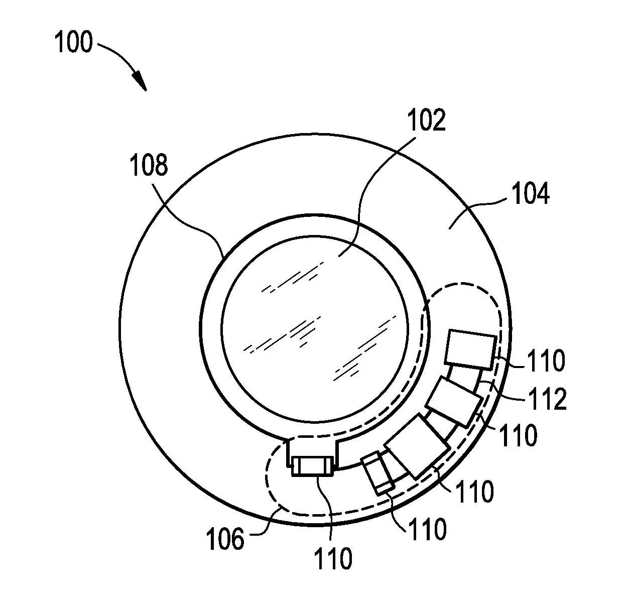
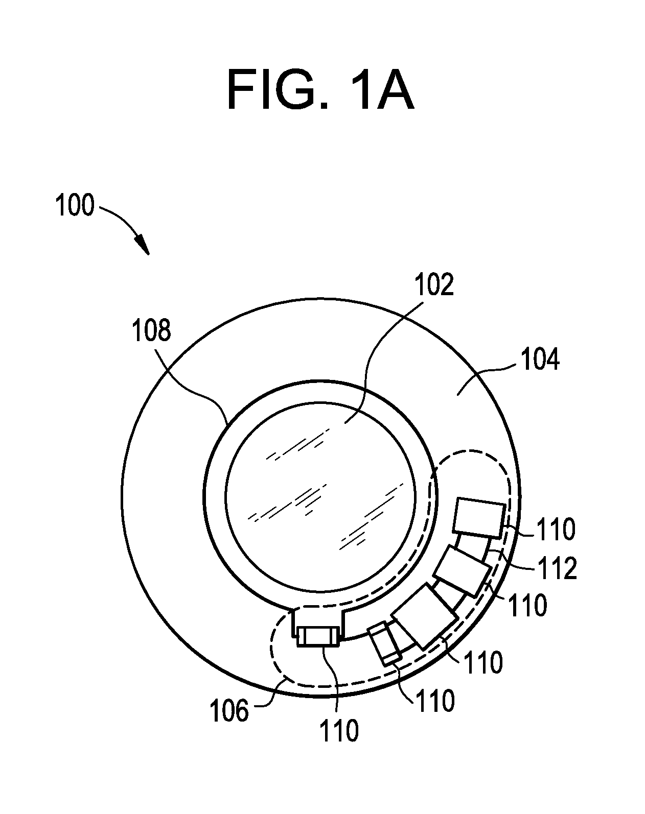
[0036]Referring to FIG. 1A there is illustrated a first exemplary embodiment of an optical lens assembly 100. Although illustrated as a contact lens, it is important to note that the present invention may be utilized in conjunction with any number of devices having medical and ophthalmic applications as well as any devices incorporating lenses, such as cameras, binoculars and microscopes. The exemplary optical lens assembly 100 comprises a lens structure 102, a circuit board 104, an electronic circuit 106 positioned on the circuit board 104, and a single turn loop antenna 108 also positioned on the circuit board 104 so as not to interfere with the lens structure 102. As utilized herein, the lens structure 102 may include a portion of an assembly that acts as an optical lens and not necessarily a separate component, but rather a region of a component such as a hydrogel overmolding. The electronic circuit 106 and the antenna 108 may be connected to or mounted to the circuit board 104 ...


PUM


Abstract

Antennas and antenna systems may be designed and configured for incorporation into mechanical devices, including medical devices, such as ophthalmic devices, including contact lenses. These antennas and antenna systems may be utilized to transmit data from the mechanical device to a receiver, to receive data from a transmitter, and/or to inductively charge an electromechanical cell or the like incorporated into the mechanical device.

Description

BACKGROUND OF THE INVENTION[0001]1. Field of the Invention[0002]The present invention is directed to optical lenses, and more particularly to optical lenses, such as wearable lenses, including contact lenses, implantable lenses, including intraocular lenses (IOLs) and any other type of device comprising an optical component that incorporates electronic circuits and associated antennas / antenna assemblies for information reception, information transmission and / or charging / energy harvesting.[0003]2. Discussion of the Related Art[0004]As electronic devices continue to be miniaturized, it is becoming increasingly more likely to create wearable or embeddable microelectronic devices for a variety of uses. Such uses may include monitoring aspects of body chemistry, administering controlled dosages of medications or therapeutic agents via various mechanisms, including automatically, in response to measurements, or in response to external control signals, and augmenting the performance of org...

Claims


Application Information

Patent Timeline
IPC IPC(8): G02C7/02A61F2/16G02C7/04
CPCA61F2/1635A61F2250/0002H01Q1/22H01Q7/00G02C7/04G02C7/049H01Q1/2225A61F2/1624B29D11/00038B29D11/00817G02C7/083A61F2250/0001A61F2/16G02C7/02
Inventor PUGH, RANDALL BRAXTONOTTS, DANIEL B.FLITSCH, FREDERICK A.TONER, ADAMHUMPHREYS, SCOTT ROBERT
Owner JOHNSON & JOHNSON VISION CARE INC
Why Eureka
Try Eureka