Image display systems

a technology of image display and display system, which is applied in the field of holographic image projectors, can solve the problems of difficult to achieve efficient semiconductor laser operation in the green region of the spectrum, and the cost of green semiconductor lasers also tends to be high, so as to facilitate the achieving of the desired output wavelength, reduce the effect of speck and good efficiency

Inactive Publication Date: 2013-08-01
LIGHT BLUE OPTICS
View PDF4 Cites 43 Cited by
  • Summary
  • Abstract
  • Description
  • Claims
  • Application Information

AI Technical Summary

Benefits of technology

[0007]In embodiments the wavelength-conversion material re-emits over a range of angles and also over a spread of wavelengths and thus decoheres the laser light, thus providing speckle reduction. In preferred implementations the wavelength conversion material is an optical downconversion material such as a ‘phosphor’. Here we use phosphor to include phosphorescent materials, fluorescent materials and quantum dot materials, though where a phosphorescent material is employed preferably this has a relatively fast decay, for example of the order of a few tens of microseconds. In some preferred implementations the wavelength-conversion material comprises a quantum dot-based material as this provides good efficiency and facilitates achieving a desired output wavelength because the emission from a quantum dot is easily tunable and can operate with small Stokes shifts. In a colour display system this facilitates a selection of red, green and blue wavelengths, for example to match these to the wavelength response of the human eye to achieve maximum perceived brightness. Further the difference between the input and output wavelengths can be small thus enabling, for example, a UV (ultraviolet) pumped wavelength-conversion material to emit in the blue. In embodiments, with either a blue or uv laser, the wavelengths of the displayed image are respectively within 3% of 613 nm, 550 nm and 459 nm.
[0008]For materials science related reasons it is difficult to achieve efficient semiconductor laser operation in the green region of the spectrum (and green semiconductor lasers also tend to be expensive). Thus in either a monochrome or a colour display system, In some preferred embodiments the laser wavelength is shorter than around 490 nm, and the output wavelength is longer than the laser wavelength, in embodiments longer than 490 nm. Thus, more generally, in embodiments the laser wavelength is shorter than the upper end of the blue region of the spectrum and the output wavelength is in the green region of the spectrum. This is helpful in improving the overall (‘wall plug’) efficiency of the projector.
[0010]In preferred embodiments the one or more wavelength-conversion optical elements are, as previously mentioned, implemented by a light re-emission wheel driven by a motor. Where a blue laser is employed, for example having a wavelength less than 490 nm, one of the regions or sectors of the wheel may comprise a transparent or diffusing region. Where a UV laser is employed each of the regions or sectors of the wheel may comprise a wavelength conversion material such as a phosphor, fluorescent or more preferably a quantum dot material. As previously mentioned, quantum dots are favoured with UV illumination because they can operate with a small difference between the exciting and output wavelength and thus facilitate blue re-emission from a UV pump.
[0014]In some preferred implementations the holographic image projector employs two spatial light modulators, a first as previously described displaying the hologram forming the real image on the first intermediate real image plane, and a second spatial light modulator at a second intermediate image plane to intensity modulate the real image. This second SLM may comprise, for example, a digital micro mirror device such as the Texas Instruments DLP™, or a liquid crystal on silicon (LCOS) SLM, or some other SLM technology. Preferably the resolution of the second SLM is greater than that of the first SLM, and the projector includes an image processor to decompose the image data into a lower spatial frequency component used to generate the hologram data, and a higher spatial frequency component for intensity modulating a real image from the hologram. This dual modulation architecture provides a number of advantages including physical compactness and improved image resolution and contrast.
[0018]In a further related aspect the invention provides a method of reducing speckle in a laser-based image projector, the method comprising: illuminating a spatial light modulator (SLM) with light at laser wavelength from a laser light source; generating a real image at said laser wavelength with light from said SLM in a first intermediate image region within said projector; wavelength-converting said real image at said laser wavelength to an output wavelength different to said laser wavelength using a layer of wavelength-converting material in said first intermediate image region; and projecting light from said real image at said output wavelength to provide a displayed image.

Problems solved by technology

For materials science related reasons it is difficult to achieve efficient semiconductor laser operation in the green region of the spectrum (and green semiconductor lasers also tend to be expensive).

Method used


Image

  • Image display systems
  • Image display systems
  • Image display systems

Examples


Embodiment Construction

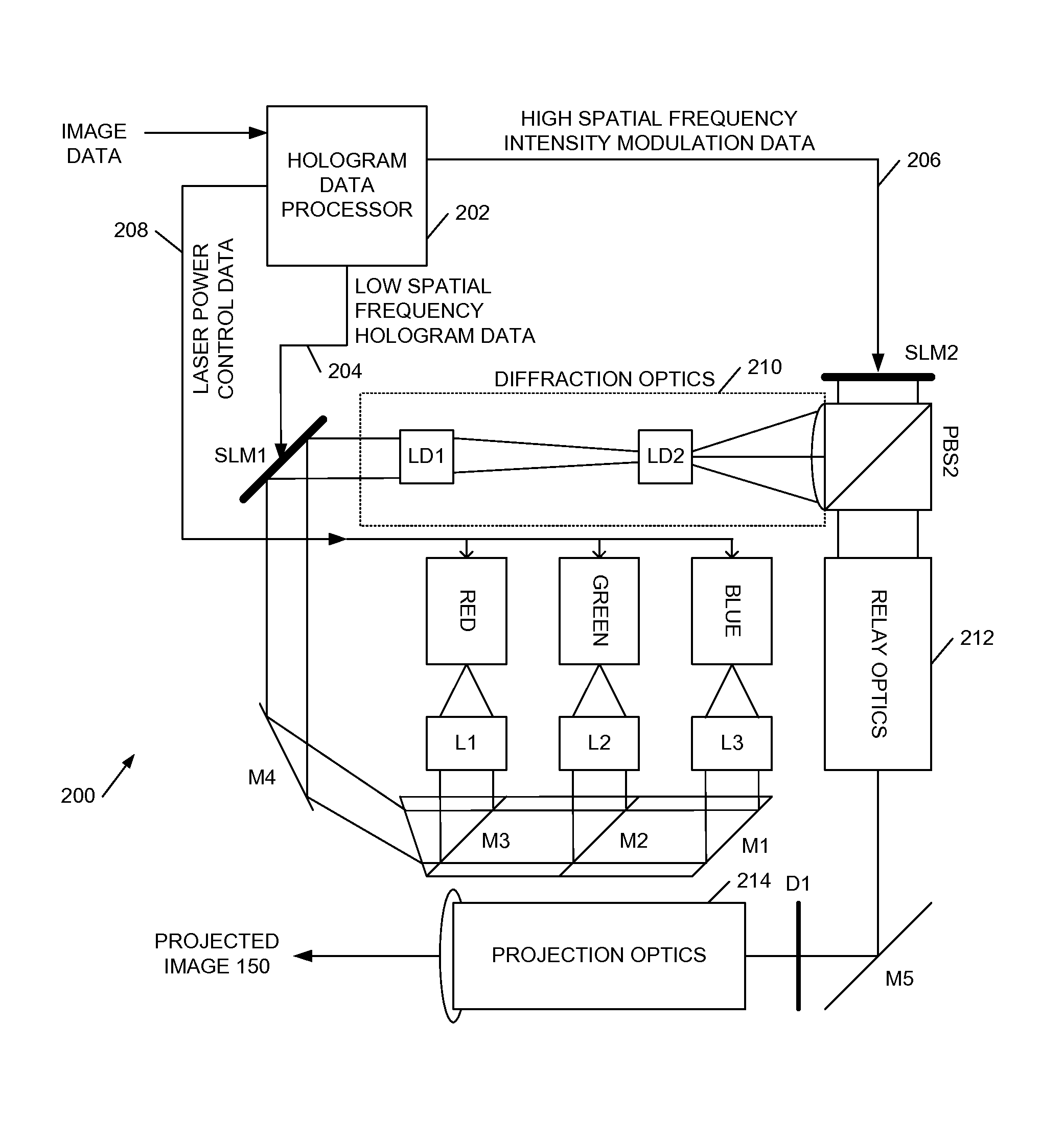
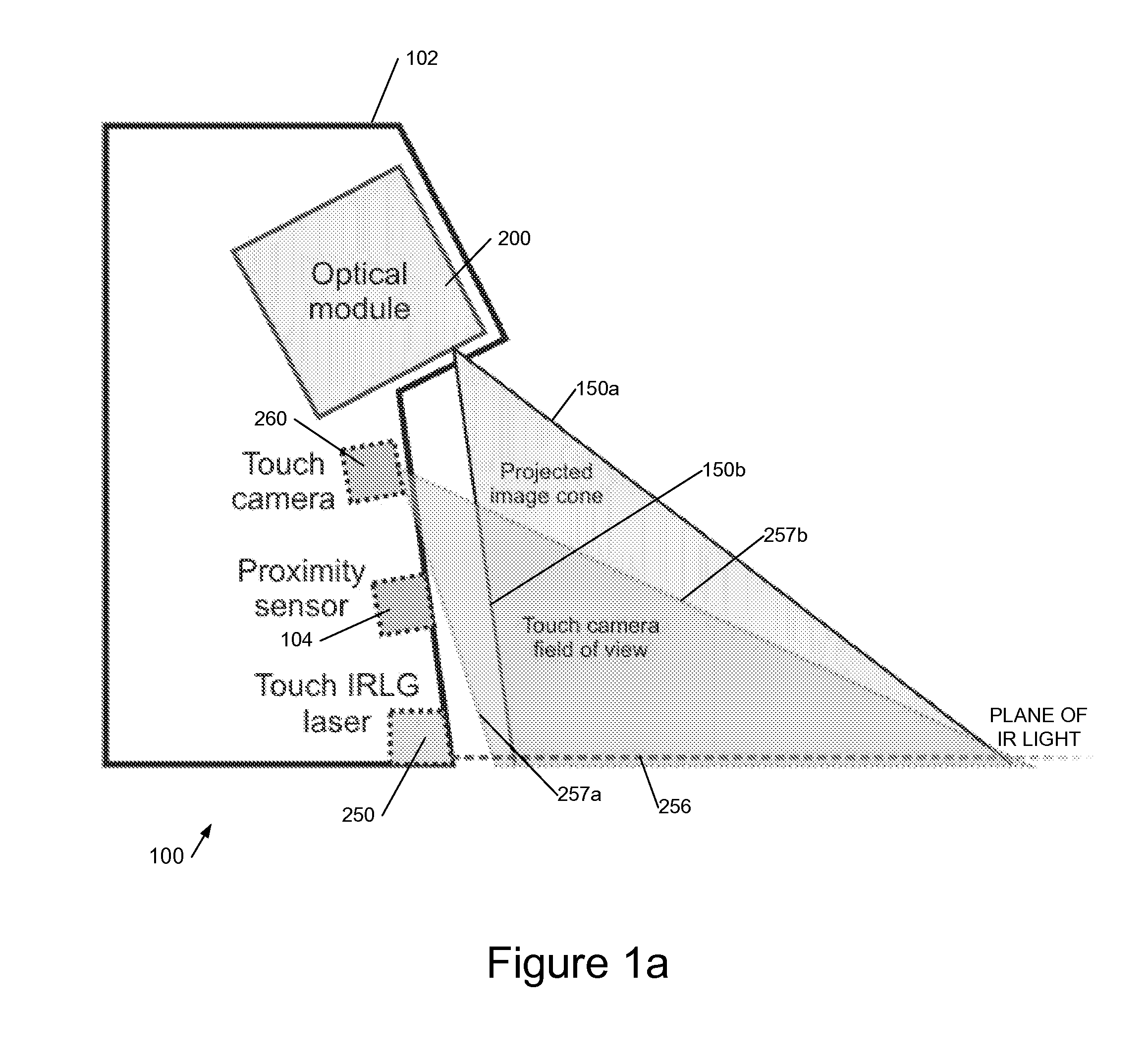
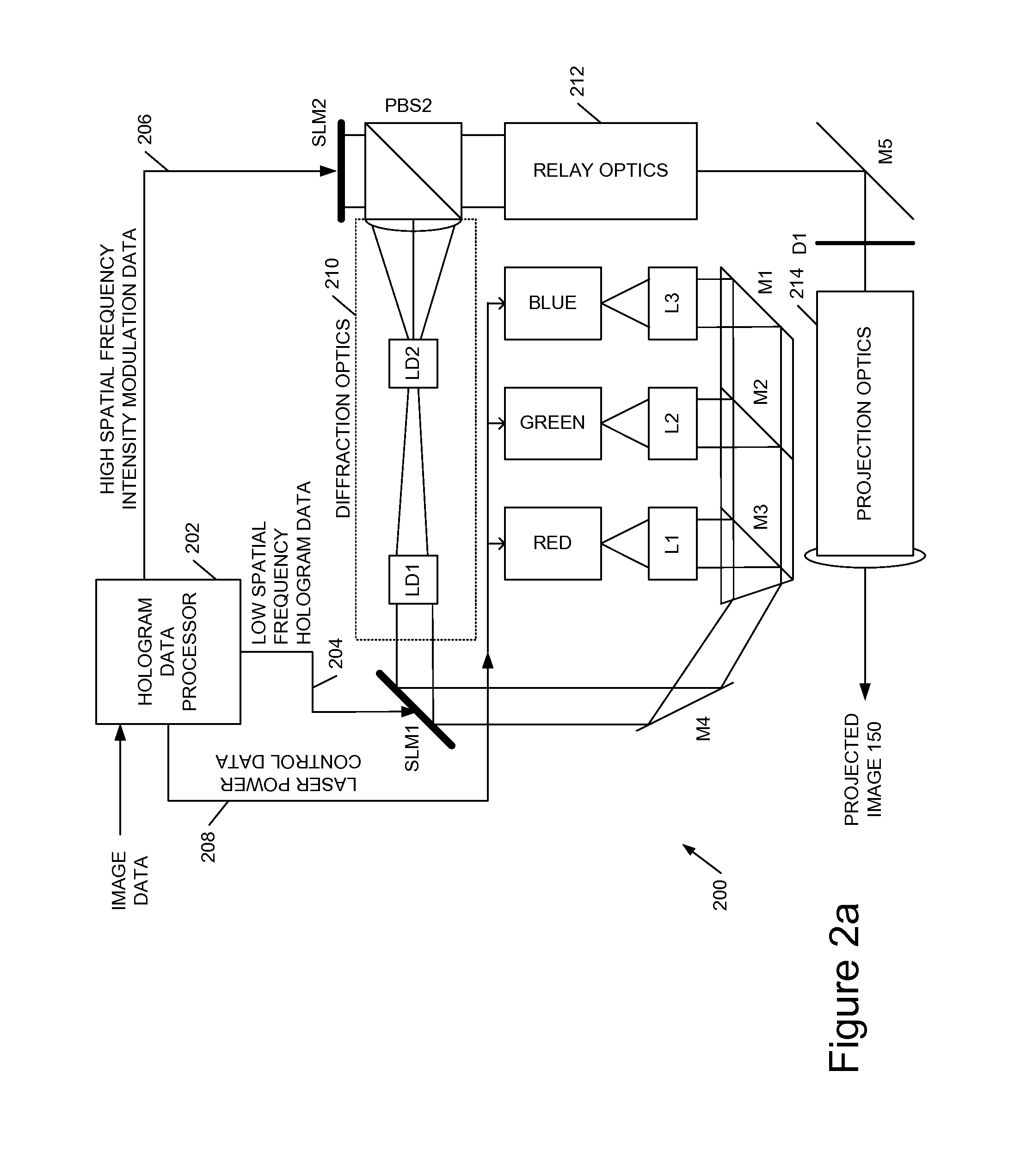
[0026]FIG. 1 shows an example holographic image projection device 100, as illustrated a touch sensitive device comprising a holographic image projection module 200 and a touch sensing system 250, 258, 260 in a housing 102. A proximity sensor 104 may be employed to selectively power-up the device on detection of proximity of a user to the device.

[0027]A holographic image projector is merely described by way of example; the techniques we describe herein may be employed with any type of image projection system.

[0028]As illustrated the holographic image projection module 200 is configured to project downwards and outwards at an acute angle onto a flat display surface such as a tabletop, but additionally or alternatively it may project forwards generally perpendicularly towards a display surface. A holographic image projector is particularly suited to acute angle projection because it can provide a wide throw angle, long depth of field, and substantial distortion correction without signi...


PUM


Abstract

We describe a holographic image projector, comprising: a laser light source to provide light at a laser wavelength; a first spatial light modulator (SLM) to display a hologram, wherein said first SLM is illuminated by said laser light source; intermediate image optics to provide a first intermediate real image plane at which a real image produced by said hologram displayed on said first SLM is formed; a wavelength-conversion material located at said first intermediate real image plane to convert said laser wavelength to at least a first output wavelength different to said laser wavelength; and second optics to project light from said real image at said output wavelength to provide a displayed image.

Description

CROSS-REFERENCE TO RELATED APPLICATIONS[0001]This application claims priority to UK application no. GB1201495.7, filed Jan. 30, 2012. This United Kingdom application is hereby incorporated by reference as though fully set forth herein.FIELD OF THE INVENTION[0002]This invention relates to image display systems using a laser light source, more particularly to holographic image projectors.BACKGROUND TO THE INVENTION[0003]We have previously described a range of techniques for projecting an image onto a screen using holography, both directly (substantially perpendicularly) and at an acute angle. We have also described techniques for making such displays touch sensitive. Examples of our earlier published patent applications include WO2010 / 074404 and WO / 2010 / 073024 (hereby incorporated by reference).[0004]Image projection systems such as these, which employ a laser light source, are prone to speckle. It is also difficult to achieve high efficiency operation at some wavelengths, in particul...

Claims


Application Information

Patent Timeline
Patent Type & Authority Applications(United States)
IPC IPC(8): G03H1/08G02B27/48G03B21/14
CPCG03H1/2205G03H1/2294G03H2001/0061G03H2001/0216G03H2001/2215G03H2001/2271G03B33/08G03H2222/15G03H2225/24G03H2225/32G02B27/48G03B21/204G03B21/208G03H2210/20
Inventor CABLE, ADRIAN JAMESROUTLEY, PAUL RICHARDSMITH, EUAN CHRISTOPHER
Owner LIGHT BLUE OPTICS
Why Eureka
Try Eureka