Dielectric thin film element, antifuse element, and method of producing dielectric thin film element

a technology of dielectric thin film and anti-fuse elements, which is applied in the direction of fixed capacitors, stacked capacitors, and semiconductor/solid-state device details, etc., can solve the problems of raising a problem of being liable to be oxidized and corroded, and the humidity resistance of the dielectric thin film element is reduced, so as to reduce the stress applied, reduce the oxidation and corrosion of the interconnect layer, and reduce the stress

Active Publication Date: 2013-08-01
MURATA MFG CO LTD
View PDF1 Cites 12 Cited by
  • Summary
  • Abstract
  • Description
  • Claims
  • Application Information

AI Technical Summary

Benefits of technology

[0006]The present invention has been made in view of these circumstances, and an object thereof is to provide a dielectric thin film element having a high humidity resistance by alleviating the stress applied onto the interconnect layers and restraining the oxidation and corrosion of the interconnect layers.

Problems solved by technology

Also, the interconnect layers 107-1, 107-2 are in a state in which the surface thereof is exposed, thereby raising a problem of being liable to be oxidized and corroded.
Each of these problems causes decrease in the humidity resistance of the dielectric thin film element.

Method used


Image

  • Dielectric thin film element, antifuse element, and method of producing dielectric thin film element
  • Dielectric thin film element, antifuse element, and method of producing dielectric thin film element
  • Dielectric thin film element, antifuse element, and method of producing dielectric thin film element

Examples


experiment examples

[0080]Dielectric thin film elements were fabricated in the following manner.

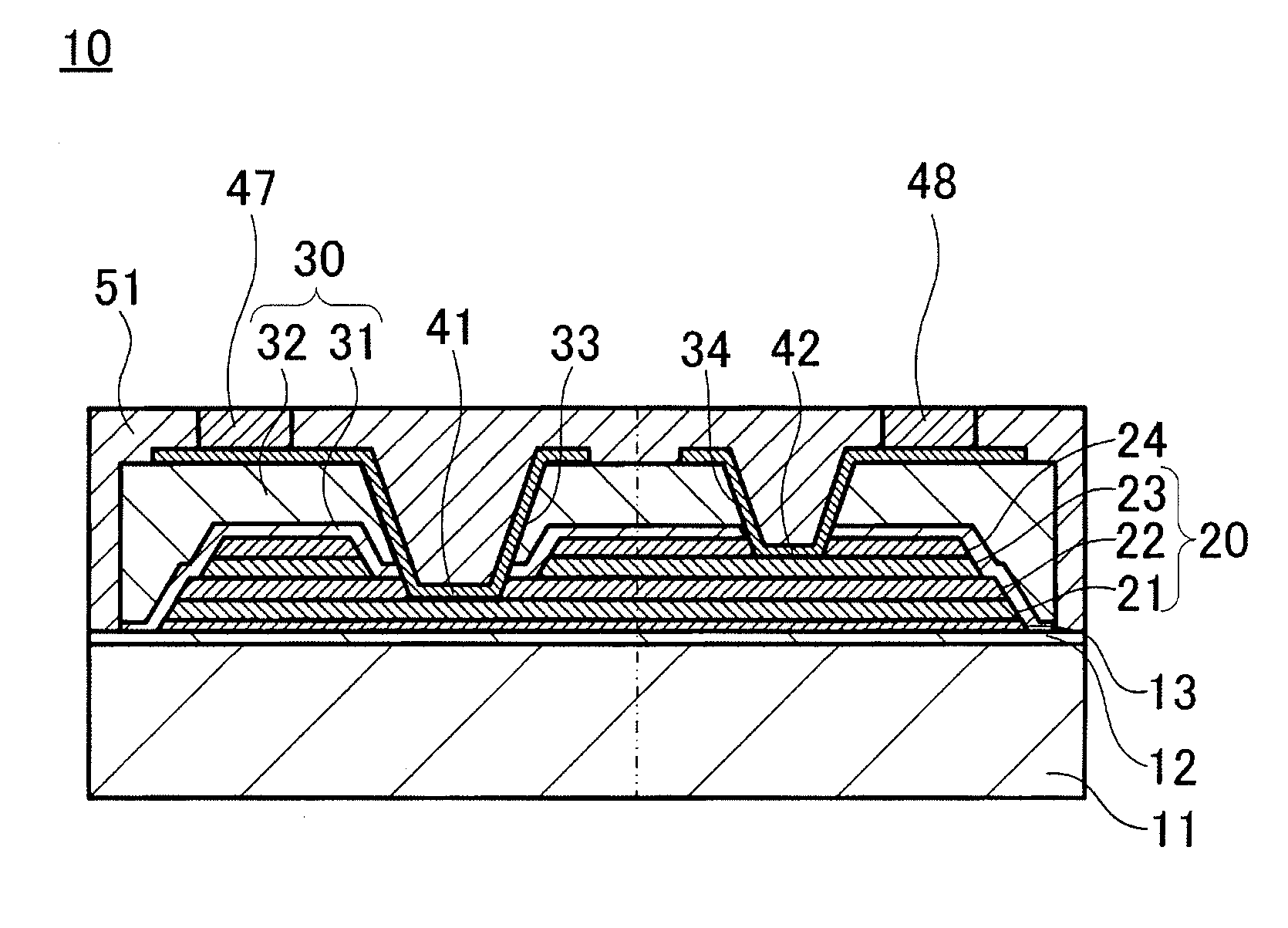
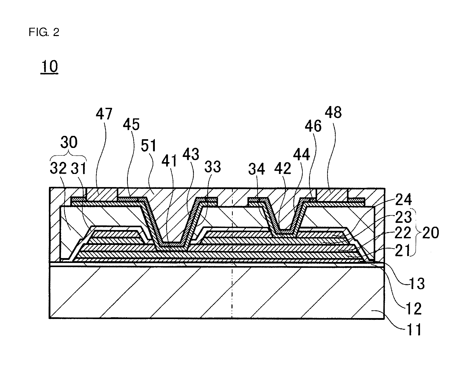
[0081]As Experiment Example 1, a dielectric thin film element such as shown in FIG. 2 was fabricated.

[0082]First, an Si substrate in which an SiO2 layer having a thickness of 700 nm had been formed as an oxide layer was prepared.

[0083]Next, a BST layer having a thickness of 50 nm was formed on the substrate as a close-adhesion layer.

[0084]Specifically, a dielectric source material solution containing an organic metal compound was applied by spin coating on the upper surface of the Si substrate in which the oxide layer had been formed, so as to attain Ba:Sr:Ti=70:30:100 (molar ratio). Thereafter, the substrate was dried under conditions of 350° C. on a hot plate. Thereafter, a thermal treatment was carried out at 650° C. for 30 minutes.

[0085]Next, a Pt layer having a thickness of 200 nm was formed on the close-adhesion layer as a lower electrode layer. The Pt layer was formed by the sputtering method.

[0086]Ne...


PUM

PropertyMeasurementUnit
thicknessaaaaaaaaaa
thicknessaaaaaaaaaa
thicknessaaaaaaaaaa

Abstract

A dielectric thin film element having a high humidity resistance is provided. A dielectric thin film element includes a capacitance section having a dielectric layer and a pair of electrode layers formed on the respective upper and lower surfaces of the dielectric layer 22. Furthermore, a protection layer is provided on the capacitance section, a pair of interconnect layers are drawn out to an upper surface of the protection layer, and external electrodes are formed to be electrically connected to the interconnect layers. Further, first surface metal layers cover a portion of the interconnect layers that extends along the inner surface of the openings and second surface metal layers are formed at end of the first surface metal layers.

Description

CROSS REFERENCE TO RELATED APPLICATIONS[0001]The present application is a continuation of International Application No. PCT / JP2011 / 070219, filed Sep. 6, 2011, which claims priority to Japanese Patent Application No. 2010-204668, filed Sep. 13, 2010, the entire contents of each of which are incorporated herein by reference.FIELD OF THE INVENTION[0002]The present invention relates to a dielectric thin film element and a method of producing the same. The present invention further relates to an antifuse element provided with a dielectric thin film element.BACKGROUND OF THE INVENTION[0003]In recent years, researches of a dielectric thin film element used in thin film capacitors, antifuse elements, and the like are eagerly carried out. As a conventional dielectric thin film element, for example, the one disclosed in Patent Document 1 is known in the art. Referring to FIG. 16, this dielectric thin film element includes a lower electrode layer 102, a dielectric layer 103, an upper electrode...

Claims


Application Information

Patent Timeline
Patent Type & Authority Applications(United States)
IPC IPC(8): H01G4/33
CPCH01L23/5223H01G4/33H01L27/016H01L23/5252H01L23/528H01L23/53257H01L23/53261H01L2924/0002
Inventor NAKAISO, TOSHIYUKITAKESHIMA, YUTAKAISHIURA, YUTAKAIRIE, YUJITANI, SHINSUKETAKAGI, JUN
Owner MURATA MFG CO LTD
Why Eureka
Try Eureka