
Formation of silicon carbide-silicon nitride nanoparticle carbon compositions

a technology of silicon carbide and silicon nitride, which is applied in the direction of carbides, other chemical processes, manufacturing tools, etc., can solve the problems of brittleness of silica, poor quality material, low impact resistance and low fracture toughness

Active Publication Date: 2013-08-01
THE UNITED STATES OF AMERICA AS REPRESENTED BY THE SECRETARY OF THE NAVY
View PDF7 Cites 15 Cited by
  • Summary
  • Abstract
  • Description
  • Claims
  • Application Information

AI Technical Summary

Benefits of technology

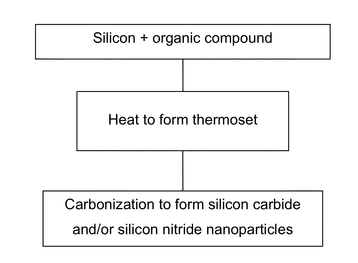
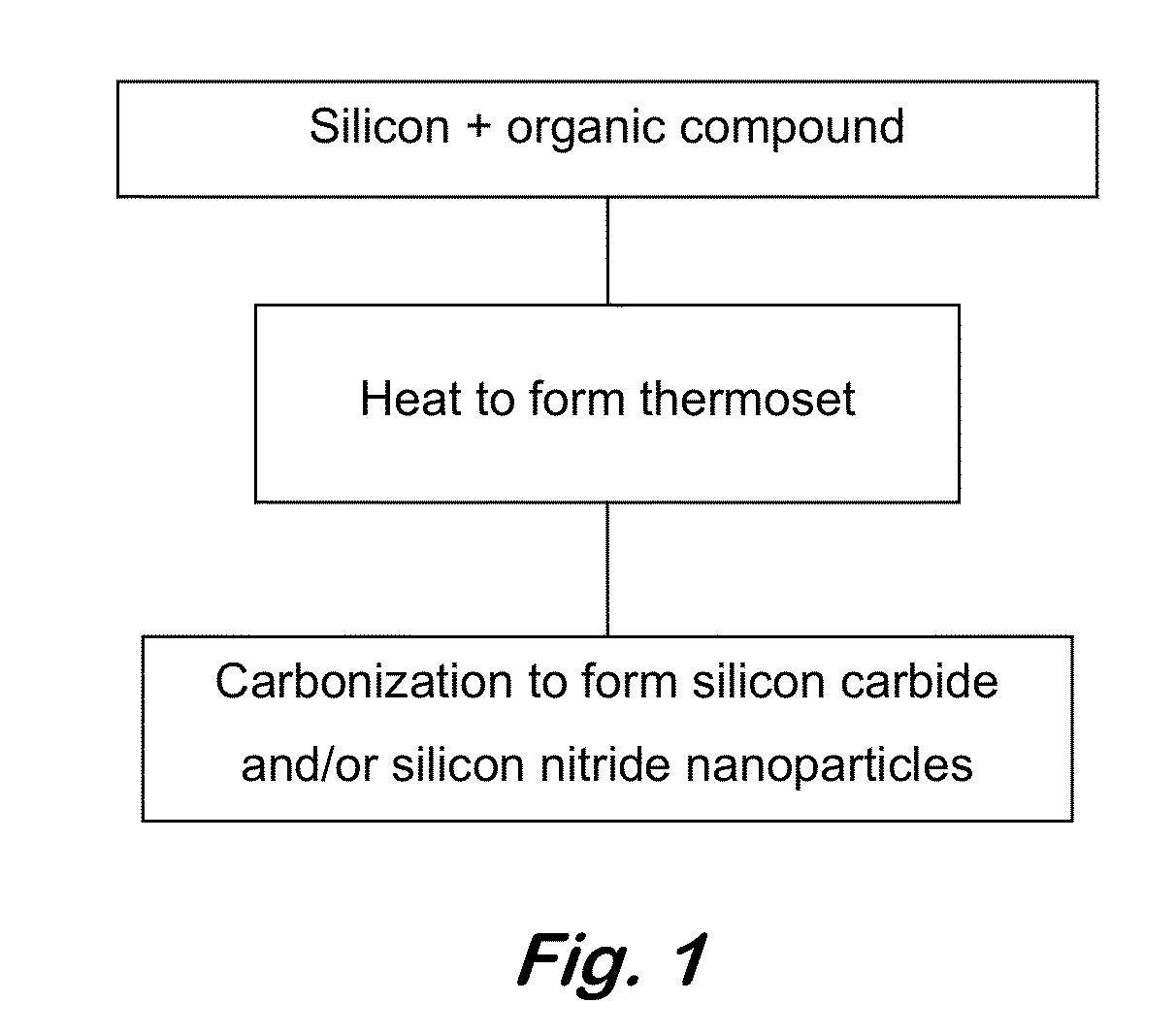
The patent describes a way to make a composition by combining nanoparticles of silicon carbide with a carbonaceous matrix or silicon matrix. The composition is formed by heating a precursor mixture of silicon and an organic compound in a controlled atmosphere. The resulting composition has improved properties, such as better thermal conductivity and higher mechanical strength. The patent also describes a method for making a ceramic with nanoparticles of silicon carbide or silicon nitride in a carbonaceous or silicon matrix. This method involves heating the precursor mixture in an inert atmosphere at high pressure and temperature to cause polymerization of the organic compound and formation of the ceramic.

Problems solved by technology

It is brittle and its density is 3.2 g / cm3.
In shaped components, SiC is brittle and is fabricated from the powder by the sintering technique at high temperature and pressure.
The conventional carbothermal reduction method for the synthesis of SiC powders is an excessive demanding energy process and leads to a rather poor quality material.
In addition, it has low impact resistance and low fracture toughness.
Moreover, fast switching has the potential to reduce the filtering passive component size and cost and thus, the total cost of the system.
The challenges involved have been considerable.
Early ceramic materials were not able to withstand these conditions and early turbine-component designs were not compatible with brittle materials.
Technological evolution has to be made over a broad front and progress has been slow.
These materials have intermediate strengths between reaction-bonded and hot-pressed materials, but they have the potential to be fabricated to near-net shape at costs competitive with metal turbine components.

Method used


Image

  • Formation of silicon carbide-silicon nitride nanoparticle carbon compositions
  • Formation of silicon carbide-silicon nitride nanoparticle carbon compositions
  • Formation of silicon carbide-silicon nitride nanoparticle carbon compositions

Examples


example 1

Formulation of Precursor Composition of TPEB and Silicon Powder (1 to 5 μm Particle Size) in Molar Ratio of 1 to 50

[0063]TPEB (0.250 g; 0.523 mmol) and silicon powder (1 to 5 μm particle size) (0.732 g, 26.1 mmol) were thoroughly mixed and used as the precursor composition for the formation of refractory nanoparticle SiC embedded or bonded with the excess of silicon that behaves as a matrix material. The ratio of the two reactants can be readily varied by the described formulation method.

example 2

Conversion of Precursor Composition of TPEB and Silicon Powder (1 to 5 μm Particle Size) in Molar Ratio of 1 to 50 to Polymeric Thermoset Solid in an Argon Atmosphere

[0064]A sample (75.2450 mg) of the precursor composition of Example 1 was weighed into a TGA ceramic pan, packed thoroughly, flushed with flow (110 cc / min) of argon for 20 minutes, and then heated at 5° C. / min to 250° C. and held at this temperature for 1 hr to consolidate to a shaped thermoset solid from reaction of the ethynyl units of TPEB.

example 3

Conversion of Polymeric Thermoset Solid to Shaped Silicon Carbide-Silicon Matrix Solid Ceramic Composition by Heating to 1450° C. Under an Argon Atmosphere

[0065]The solid polymeric thermoset of Example 2 was heated under a flow (110 cc / min) of argon at 3° C. / min to 1200° C. and held at this temperature for 1 min followed by heating at 1° C. / min to 1415° C. and holding at this temperature for 1 hr and at 1 ° C. / min to 1450° C. and holding at this temperature for 1 hr. The resulting solid ceramic sample retained 90.45% of the original weight. XRD analysis showed the formation of pure silicon carbide nanoparticles / nanostructures embedded in a matrix of crystalline Si nanostructure.


PUM

PropertyMeasurementUnit
Temperatureaaaaaaaaaa

Abstract

A composition having nanoparticles of silicon carbide and a carbonaceous matrix or silicon matrix. The composition is not in the form of a powder. A composition having silicon and an organic compound having a char yield of at least 60% by weight or a thermoset made from the organic compound. A method of combining silicon and the organic compound and heating to form silicon carbide or silicon nitride nanoparticles.

Description

[0001]This application claims the benefit of U.S. Provisional Application No. 61 / 693,930, filed on Aug. 28, 2012. This application is a continuation in part application of U.S. Nonprovisional patent application Ser. No. 13 / 779,771, filed on Feb. 28, 2013, which is a continuation in part application of U.S. Nonprovisional patent application Ser. No. 13 / 768,219, filed on Feb. 15, 2013, which is a continuation in part application of U.S. Nonprovisional patent application Ser. No. 13 / 749,794, filed on Jan. 25, 2013, which claims priority to U.S. Provisional Application No. 61 / 590,852, filed on Jan. 26, 2012, U.S. Provisional Application No. 61 / 640,744, filed on May 1, 2012, U.S. Provisional Application No. 61 / 669,201, filed on Jul. 9, 2012, and U.S. Provisional Application No. 61 / 693,930, filed on Aug. 28, 2012. These applications and all other publications and patent documents referred to throughout this nonprovisional application are incorporated herein by reference.TECHNICAL FIELD[00...

Claims


Application Information

Patent Timeline
IPC IPC(8): C04B35/573
CPCC01B31/36B82Y30/00C04B35/524C04B35/76C04B35/806C04B35/83C04B2235/383C04B2235/3834C04B2235/3873C04B2235/421C04B2235/422C04B2235/428C04B2235/48C04B2235/5216C04B2235/5248C04B2235/526C04B2235/5288C04B2235/5436C04B2235/6562C04B2235/762C04B2235/767C04B2235/77C04B2235/781C04B2235/80C04B2235/95C04B35/573C04B35/52C04B35/591C04B35/522C01B32/956Y10T428/249957Y10T428/249956C01B32/991C01B32/984C04B35/80
Inventor KELLER, TEDDY M.SAAB, ANDREWLASKOSKI, MATTHEWQADRI, SYED B.
Owner THE UNITED STATES OF AMERICA AS REPRESENTED BY THE SECRETARY OF THE NAVY
Learn More