
Molten salt solar receiver and procedure to reduce the temperature gradient in said receiver

a technology of solar receiver and molten salt, which is applied in the field of high concentration solar thermoelectricity, can solve the problems of short operating period, molten salt receiver sections can present various difficulties, and the effect of short operating period

Active Publication Date: 2013-08-08
ABENGOA SOLAR NEW TECH SA
View PDF25 Cites 9 Cited by
  • Summary
  • Abstract
  • Description
  • Claims
  • Application Information

AI Technical Summary

Benefits of technology

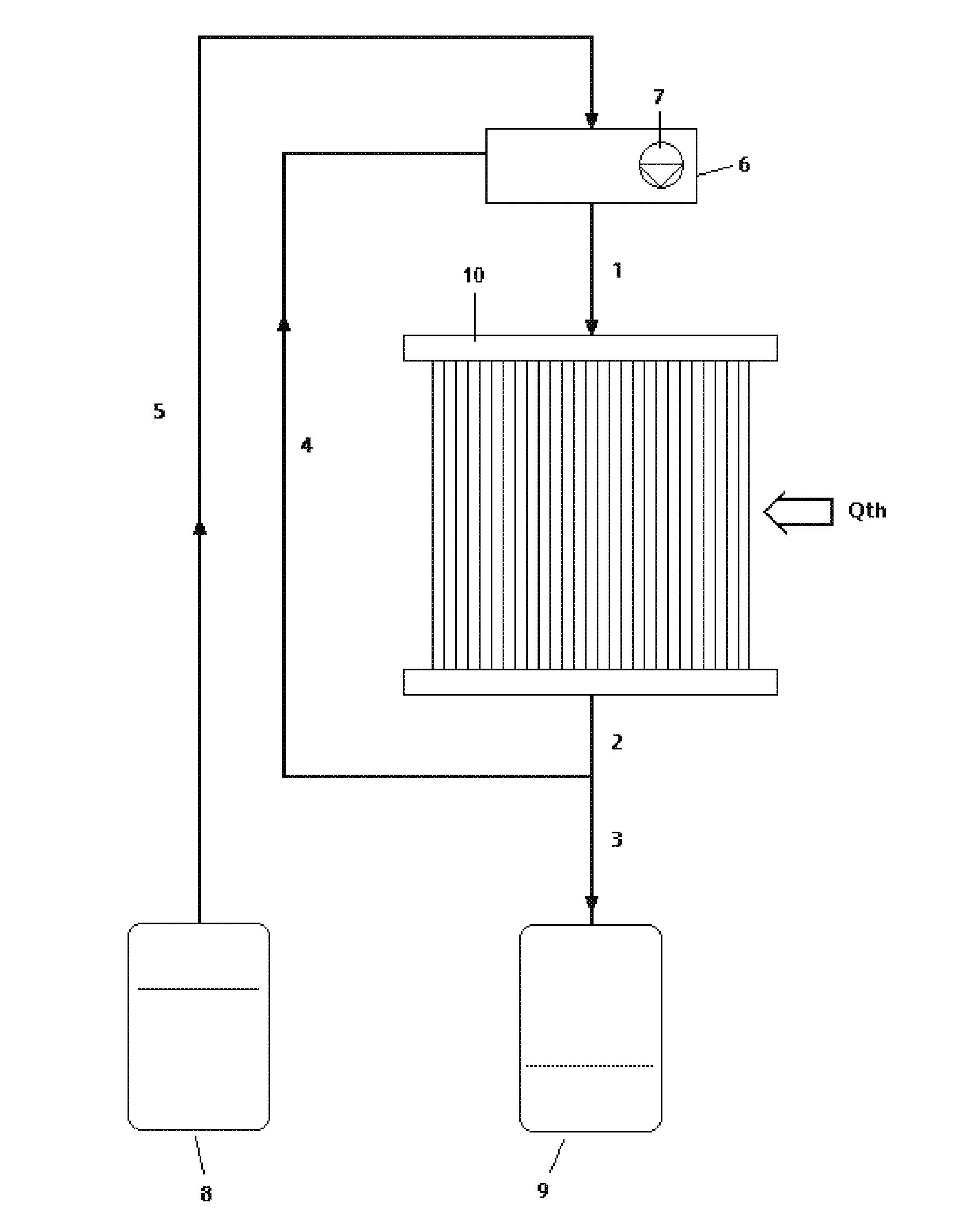
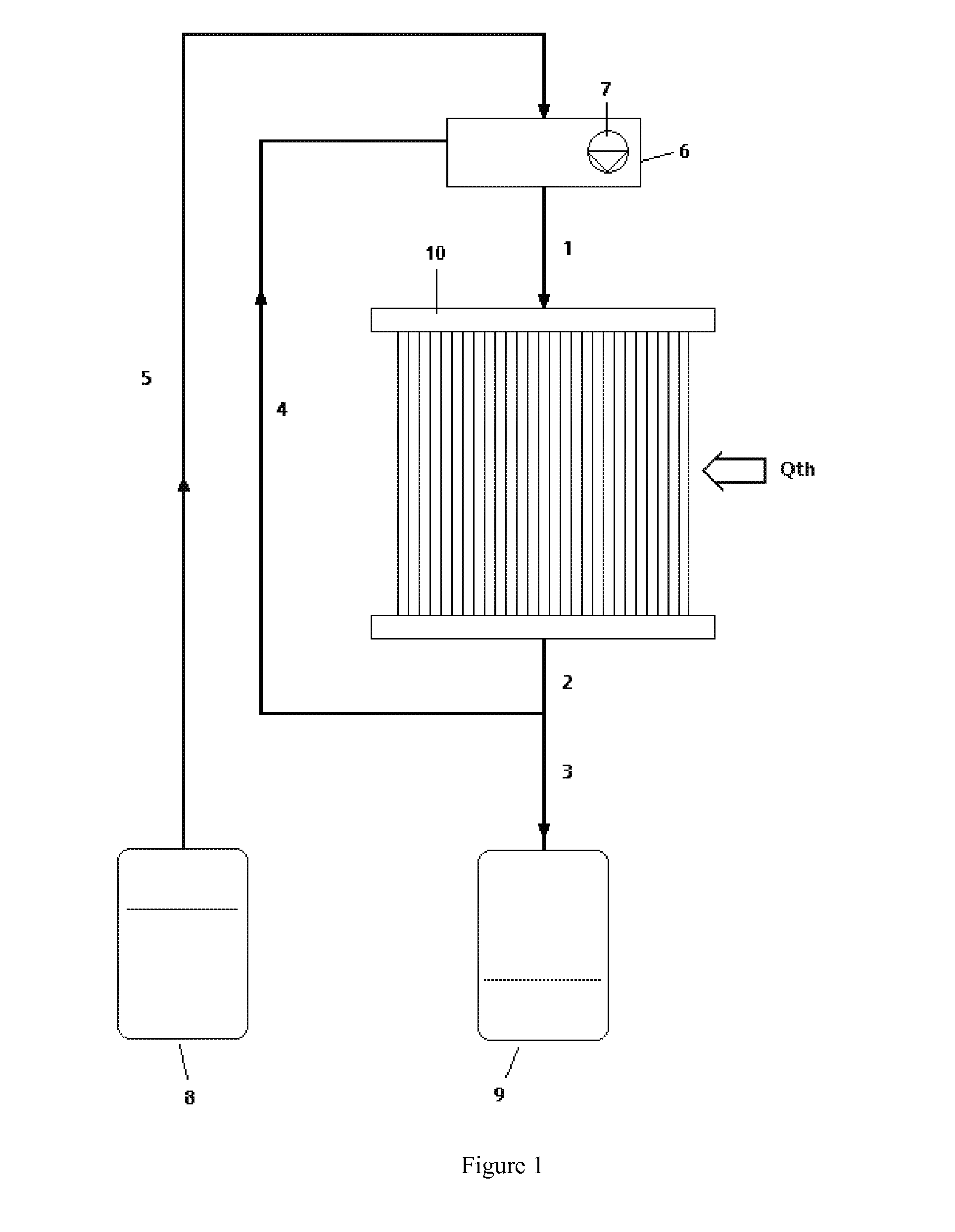
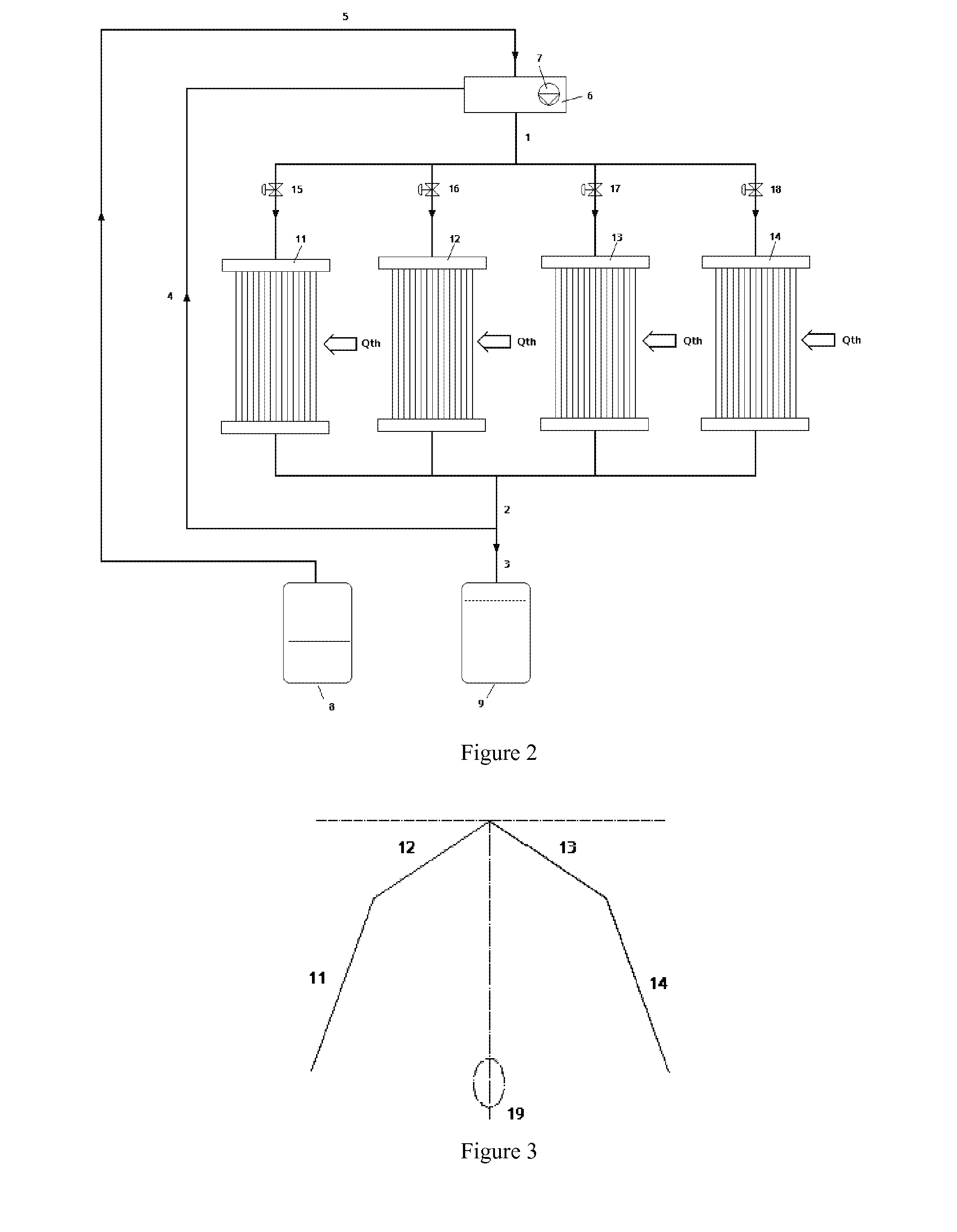
The invention proposes a central tower receiver for a thermoelectric solar plant that uses molten salts. The design allows for increased lifespan and reduced temperature differences between the receiver's entrance and exit, which can lead to structural damage. To achieve this, the invention proposes recirculation of a percentage of the exit flow of the receiver, which must result in the lowest possible load loss while generating acceptable thermal losses for a set level of receiver efficiency.

Problems solved by technology

The salt towers hitherto existent have presented technical and economical difficulties that have led to short operating periods, which is not viable for a commercial plant in which life spans of between 20 years and 25 years are demanded.
The technical problems presented during operation in these plants are mainly related to the resistance of the materials and to the control of the system during transitory states (passing of clouds).
Some of the technical difficulties encountered were the appearance of cracks in the sections of the pipes welded to the collectors, where the entrance and exit of the working fluids (headers) take place.
This is due to high thermal gradients, the corrosion of the valves for flow distribution control caused by the highly corrosive effect of the mixture of molten salts at high working temperatures, the solidification of the heat transfer fluid inside the pipes especially in areas with a low flow of incident radiation, etc.
According to that explained previously, the molten salt receivers can present various difficulties such as for example, large thermal losses if dealing with an external receiver and structural damage due to the high operating temperatures, the distribution of incident flow (not uniform), thermal tensions to which the material is subjected and the effects of corrosion on the material.

Method used


Image

  • Molten salt solar receiver and procedure to reduce the temperature gradient in said receiver
  • Molten salt solar receiver and procedure to reduce the temperature gradient in said receiver
  • Molten salt solar receiver and procedure to reduce the temperature gradient in said receiver

Examples


Embodiment Construction

[0018]This invention proposes the design of a central tower receiver using molten salts with a defined configuration, which facilitates its functioning and control during the operation of the thermoelectric solar plant.

[0019]The main advantage of the design which is the object of this invention is that its implementation allows the useful life of the receiver to be increased and a decrease in the differences in temperature between the feed entrance and exit in the pipes which the receiver is composed of. As a consequence, there would be a reduction in the thermal tensions experienced by the material which can result in structural damage, such as fractures and cracks, mainly in the welded areas.

[0020]To achieve this, a system is proposed involving recirculation of a percentage of the exit flow of the receiver (mixture of hot molten salts) upon their entrance. This flow percentage must result in the lowest possible load loss, generating at the same time admissible thermal losses for a...


PUM


Abstract

Molten salt solar receiver and procedure to reduce the temperature gradient in said receiver. The receiver consists of at least one panel of semi cylindrical geometry, formed by a combination of vertical pipes. The receiver (10) is supplied with a heat transfer fluid made up of molten salts which originate from a recirculation system which is composed of a mixture deposit (6), a hot salt storage tank (9) and a cold salt storage tank (8); the mixture tank (6) which is supplied by a part of the hot heat transfer fluid (4) which exits the receiver (10) and the cold heat transfer fluid (5) which exits the cold salt storage tank (8); the hot salt storage tank is connected to the exit of the receiver (10) so that a part of the heat transfer fluid which does not recirculate is stored (3).

Description

TECHNICAL FIELD OF THE INVENTION[0001]This invention belongs to the technical field of high concentration solar thermoelectricity. It is based on solar central tower technology with heliostat fields for the generation of electrical energy. A mixture of molten salts are used in the receiver as a heat transfer fluid which allows high working temperatures to be reached and, consequently, increases the efficiency of the thermodynamic cycle with respect to the use of water / steam as a heat transfer fluid.BACKGROUND OF THE INVENTION[0002]Found within the technical field of high concentration solar thermoelectricity are solar central tower systems in which direct solar radiation is reflected by a field of heliostats towards the receiver, situated on the upper part of the tower (optical system focus). The receiver is the system where all the solar radiation coming from the solar field concentrates. This solar energy transforms into the thermal energy of the heat transfer fluid. In the event ...

Claims


Application Information

Patent Timeline
Patent Type & Authority Applications(United States)
IPC IPC(8): F24J2/46F24S10/70F24S20/20
CPCF24J2/07F24J2/34F24J2/4649F28D20/028F28D2020/0047F24J2/46Y02E10/46Y02E70/30Y02E10/41Y02E60/145F28D2020/006F24S20/20F24S80/20F24S60/10Y02E10/50Y02E10/44Y02E60/14F24S10/70F24S80/00F03G6/02F03G6/06Y02E10/40
Inventor NAVIO GILABERTE, RAULLLORENTE FOLCH, PAULAROMERO DELGADO, MARIA DEL CARMEN
Owner ABENGOA SOLAR NEW TECH SA
Learn More