
System and method for maintaining aircraft ground travel speed and direction

a technology for maintaining aircraft ground speed and direction, applied in vehicle position/course/altitude control, process and machine control, instruments, etc., can solve problems such as increased risk of ground incidents involving aircraft, ground vehicles, passengers and ground personnel, and reduced maneuvering space in the ramp area

Active Publication Date: 2013-08-08
BOREALIS TECH LTD
View PDF8 Cites 34 Cited by
  • Summary
  • Abstract
  • Description
  • Claims
  • Application Information

AI Technical Summary

Benefits of technology

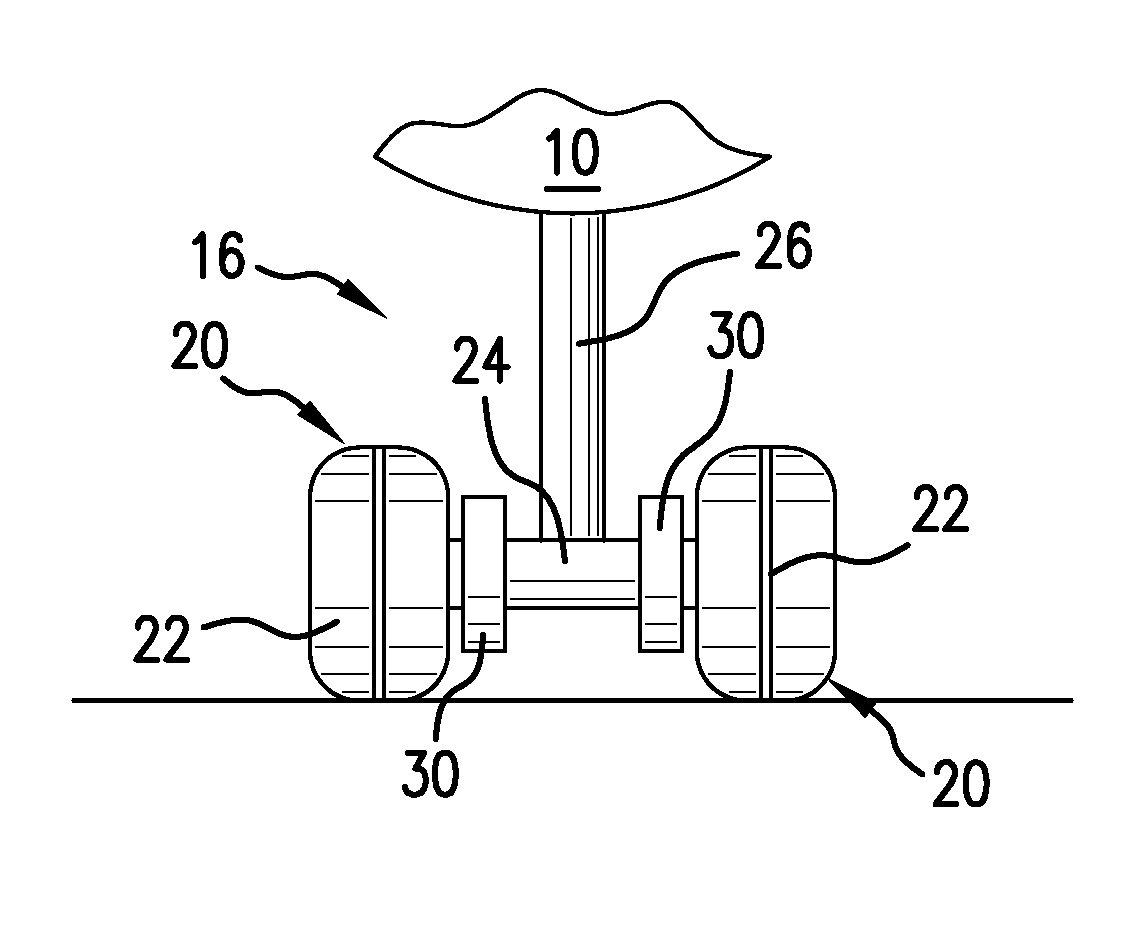
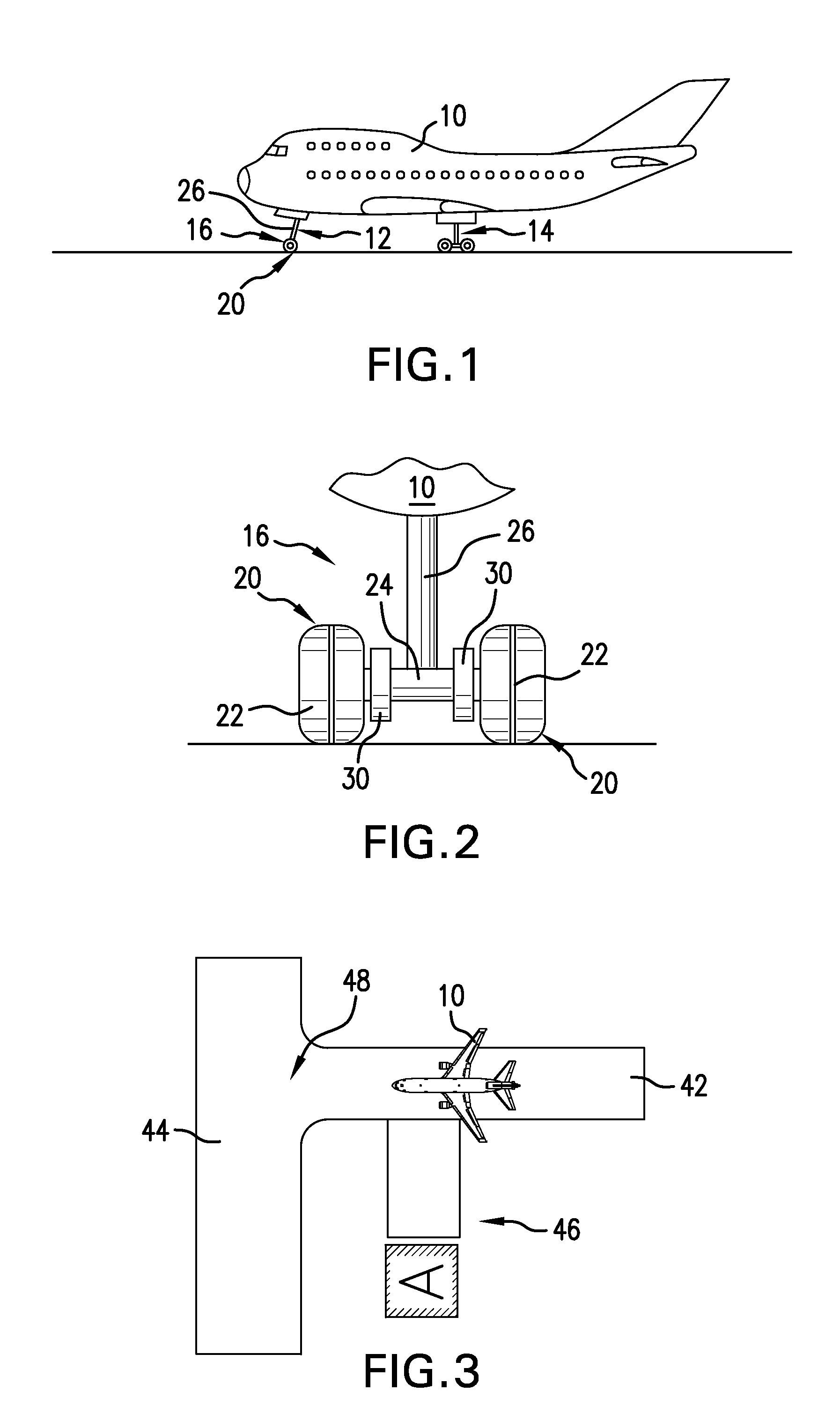
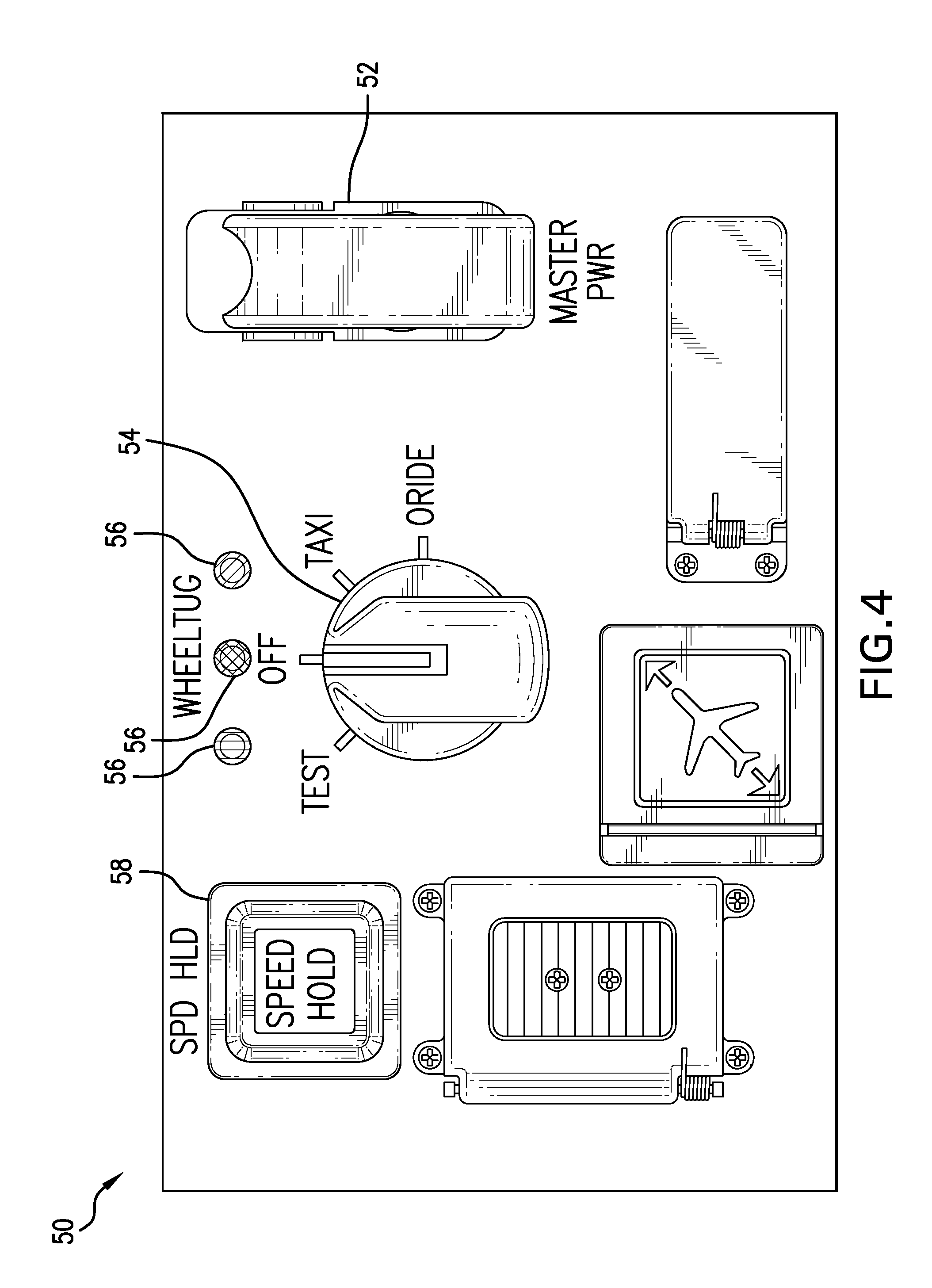
The present invention provides a method for automatically setting, controlling, or maintaining a selected aircraft travel speed during taxi in an aircraft equipped with drive means that powers one or more aircraft wheels to move the aircraft during ground travel without the use of aircraft engines. It also provides a system and method for automatically controlling the direction of ground travel in an aircraft equipped with drive means that powers one or more aircraft nose wheels to move the aircraft during ground travel without the use of aircraft engines. Additionally, it allows for minimal pilot input and leaves the pilot free to concentrate on other aircraft taxi tasks. Furthermore, it can be retrofitted in an existing aircraft and interface with sensors located outside the aircraft to automatically guide the aircraft along a selected travel route between landing, arrival at an airport gate, departure from an airport gate, and takeoff.

Problems solved by technology

The increased aircraft ground traffic found at many airports, however, may be accompanied by an increased risk of ground incidents involving aircraft, ground vehicles, and even passengers and ground personnel.
Runway and ramp congestion caused by increasing numbers of flights, stringent aircraft scheduling requirements, and efforts to squeeze large jets into gates originally designed for much smaller aircraft all contribute to airport traffic jams and reduced maneuvering space in the ramp area.
Some studies have indicated that the location of most of the incidents resulting in damage that occur during aircraft ground travel happen at the ramp entry or exit area.
This is difficult to do when a pilot must focus not only on careful operation of the aircraft engines during taxi, but also on the aircraft travel speed as the pilot tries to achieve a required time of arrival at a specified traffic flow point at a busy airport.
One study of pilots using a simulation of this type of airport surface traffic management system during taxi-out departure from the ramp area to the runway indicated that pilots had more difficulty maintaining a commanded speed for a long distance and spent a significant amount of time with heads down looking at a speed display.
(Bakowski et al, Proceedings of the Sixteenth International Symposium on Aviation Psychology, 44-49, Dayton, Ohio, Wright University, 2009) The pilots participating in the study indicated that staying within the commanded speed was not a reasonable requirement and negatively impacted safety by interfering with primary taxi tasks to navigate the aircraft and maintain visual separation from other aircraft and obstacles.
While most airports have recommended taxi speeds during aircraft ground travel after landing and prior to takeoff, it is difficult to set a firm rule that defines a safe taxi speed.
What is safe under some conditions may be hazardous under others.
Too great a taxi speed must be avoided, since high ground speeds can exert excessive strains on an aircraft and result in a lack of control on turns.
The use of an aircraft's main engines to move an aircraft on the ground presents challenges, however, ranging from the dangers associated with jet blast and engine ingestion to the reduction in useful engine life caused by ingestion of foreign object debris and continuous engine operation at low taxi speeds rather than optimal air speeds.
In addition, aircraft ground travel using the aircraft engines consumes significant amounts of fuel and increases fuel costs.
Automotive cruise and speed control systems, moreover, do not automatically control direction of travel.

Method used


Image

  • System and method for maintaining aircraft ground travel speed and direction
  • System and method for maintaining aircraft ground travel speed and direction
  • System and method for maintaining aircraft ground travel speed and direction

Examples


Embodiment Construction

[0029]The system and method of maintaining aircraft ground travel speed of the present invention permits a level of control over aircraft ground travel and taxi not heretofore possible. While autopilot systems that control aircraft travel during flight and leave the pilot and cockpit crew free to handle other flight tasks have long been available, similar systems have not been provided to control aircraft ground travel. When an aircraft touches down on an airport runway, the pilot and cockpit crew must direct the moving aircraft along the airport's runway system to an ultimate parking location. The distance and runway route to be traveled depends on the specific airport and can vary quite widely. Some airports have a limited number of runways that can be easily navigated with few turns or stops, and other airports require the cockpit crew to negotiate a more complex path between landing and arrival at a gate or other parking location. Whether an aircraft's taxi path is simple or con...


PUM


Abstract

A system and method for setting, controlling, or maintaining a selected taxi speed and route for one or more aircraft equipped with an onboard non-engine powered drive means powering one or more aircraft wheels to move the aircraft during taxi is provided. Taxi speed and / or route can be set, maintained, or controlled by the aircraft pilot or ground traffic control in conjunction with taxi speed and travel of other aircraft and ground vehicles. A pilot activates a speed control to set and control taxi speed. The aircraft will automatically travel on the ground at that speed without input from the pilot until it is necessary to change the speed manually or automatically. Airport ground traffic control can generate taxi profiles for all non-engine driven aircraft to automatically control, subject to pilot capability to override, the taxi of multiple aircraft at an airport in conjunction with ground vehicle movement.

Description

PRIORITY CLAIM[0001]This application claims priority from U.S. Provisional Application No. 61 / 530,925 filed 2 Sep. 2011, the disclosure of which is fully incorporated herein.TECHNICAL FIELD[0002]The present invention relates generally to aircraft ground travel and specifically to a system and method for maintaining a selected ground speed and travel direction during aircraft ground travel.BACKGROUND OF THE INVENTION[0003]The operation of airlines and airports today focuses on achieving maximum efficiency to keep operating costs as low as possible while continuing to provide travelers with a safe and economical mode of travel. Moving aircraft effectively on the ground between landing and takeoff improves airport operating efficiency. The increased aircraft ground traffic found at many airports, however, may be accompanied by an increased risk of ground incidents involving aircraft, ground vehicles, and even passengers and ground personnel. Improving the efficiency of airport ground t...

Claims


Application Information

Patent Timeline
Patent Type & Authority Applications(United States)
IPC IPC(8): B64C25/40
CPCB64C25/405Y02T50/823G08G5/0021G08G5/065G05D1/0083G08G5/0026Y02T50/80
Inventor GOLDMAN, JOSEPHCOX, RODNEY T.COX, ISAIAH W.
Owner BOREALIS TECH LTD
Learn More