Relaxation oscillator

a relaxation oscillator and oscillator technology, applied in the field of oscillators, can solve problems such as increasing costs

Active Publication Date: 2013-08-08
MEDIATEK INC
View PDF6 Cites 14 Cited by
  • Summary
  • Abstract
  • Description
  • Claims
  • Application Information

AI Technical Summary

Problems solved by technology

Moreover, an oscillator with a frequency tracking loop provides a stable output clock under wide supply voltag

Method used


Image

  • Relaxation oscillator
  • Relaxation oscillator
  • Relaxation oscillator

Examples


Embodiment Construction

[0020]The following description is of the best-contemplated mode of carrying out the invention. This description is made for the purpose of illustrating the general principles of the invention and should not be taken in a limiting sense. The scope of the invention is best determined by reference to the appended claims.

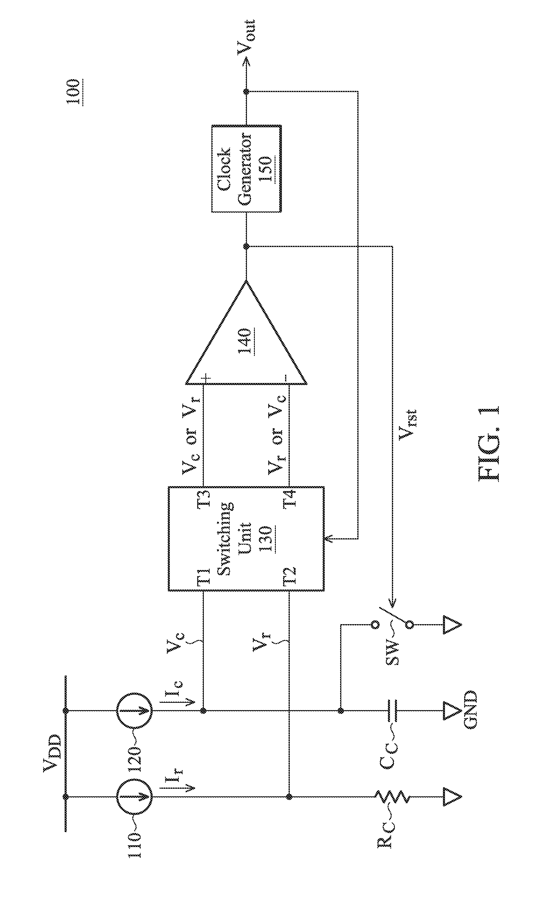
[0021]FIG. 1 shows a relaxation oscillator 100 according to an embodiment of the invention. The relaxation oscillator 100 comprises the current sources 110 and 120, a switching unit 130, a comparator 140, a clock generator 150, a resistive element (e.g., resistor RC), a capacitive element (e.g., capacitor CC) and a switch SW. The resistor RC is coupled between the current source 110 and a ground GND, and the capacitor CC is coupled between the current source 120 and the ground GND. The current source 110 coupled to a supply voltage VDD is used to provide a current Ir to the resistor RC, so as to generate a voltage Vr to a terminal T2 of the switching unit 130. The curr...


PUM


Abstract

A relaxation oscillator is provided. A first current source provides a first current. A second current source provides a second current. A resistive element is coupled between the first current source and a ground. A capacitive element is coupled between the second current source and the ground. A comparator has a non-inverting input terminal, an inverting input terminal and an output terminal for outputting a compare result. A clock generator provides a clock signal according to the compare result. A switching unit alternately couples the non-inverting input terminal and the inverting input terminal of the comparator to the resistive element and the capacitive element according to the clock signal.

Description

CROSS REFERENCE TO RELATED APPLICATIONS[0001]This application claims priority of U.S. Provisional Application No. 61 / 596,353, filed on Feb. 8, 2012, the entirety of which is incorporated by reference herein.BACKGROUND OF THE INVENTION[0002]1. Field of the Invention[0003]The invention relates to an oscillator, and more particularly to a relaxation oscillator.[0004]2. Description of the Related Art[0005]On-chip oscillators are in high demand as an external crystal replacement by low-cost and single-chip systems. The frequency stability of an oscillator against variations in temperature and supply voltage is a critical specification for an on-chip oscillator. Working with wide range of supply voltages is also preferred, to gain the most operating time when powered by a battery.[0006]In general, a wide supply range oscillator with typical frequency stability can better accommodate temperature changes. Furthermore, relaxation oscillators with voltage averaging feedback (VAF) or an offset...

Claims


Application Information

Patent Timeline
IPC IPC(8): H03K3/36
CPCH03K3/0231H03K5/2472H03K5/153H03K4/502G01R19/10H03K3/36
Inventor HSIAO, KENG-JAN
Owner MEDIATEK INC
Why Eureka
Try Eureka