Eureka AIR delivers breakthrough ideas for toughest innovation challenges, trusted by R&D personnel around the world.

Method of delaying crosslinking in well treatment operation

Inactive Publication Date: 2013-08-08
BAKER HUGHES INC
View PDF13 Cites 9 Cited by
  • Summary
  • Abstract
  • Description
  • Claims
  • Application Information

AI Technical Summary

Benefits of technology

The patent text describes a method for controlling the timing of crosslinking between a viscosifying agent and a crosslinking agent during a hydraulic fracturing operation. This is achieved by adding a crosslink delaying agent, specifically a glutamic-N,N-diacetic acid salt, to the fluid introduced into the wellbore. This delay results in a delay in the time it takes for the gel to form from the crosslinking process. The technical effect of this method is better control over the timing of the crosslinking process, which can improve the efficiency and effectiveness of hydraulic fracturing operations.

Problems solved by technology

The fluid is then pumped at rates and pressures that exceed the confining stresses in the formation, causing the formation to fail by inducing a fracture.
Typically, fracturing fluids encounter high shear while they are being pumped through the tubing which penetrates the wellbore.
Most crosslink delaying agents are ineffective when the fracturing fluid is subjected to high shear.

Method used


Image

  • Method of delaying crosslinking in well treatment operation
  • Method of delaying crosslinking in well treatment operation
  • Method of delaying crosslinking in well treatment operation

Examples


example 1

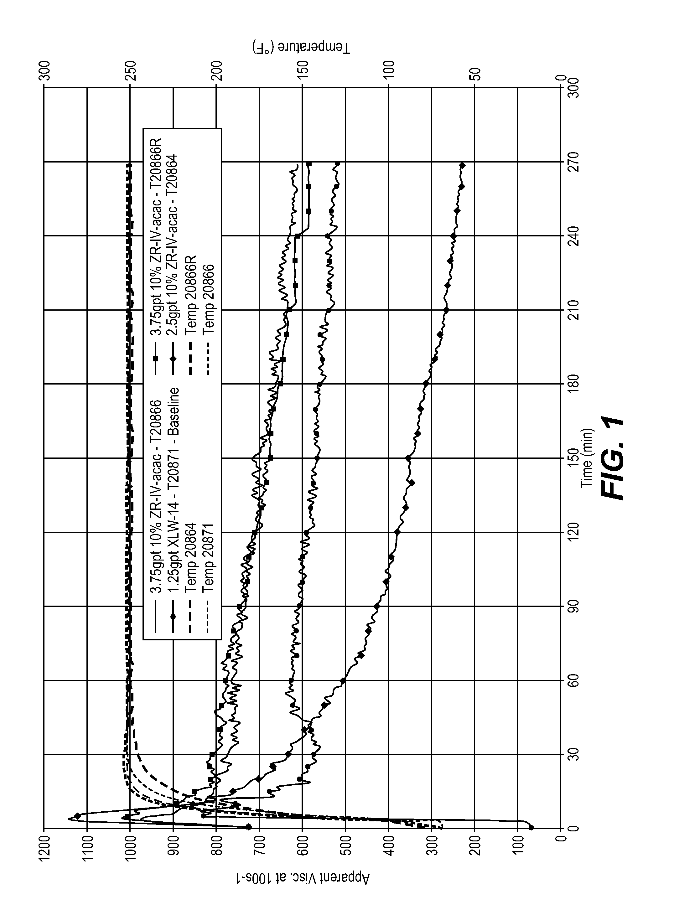
[0048]A fluid was prepared by first hydrating 1 liter of a 30 pounds per 1000 gal carboxymethyl guar linear gel for 30 minutes using a standard mixer at 1500 rpm. The contents were then poured into an OFITE sample cup and the viscosity of the linear gel was determined on a Model 900 viscometer, commercially available from OFI Testing Equipment, Inc. (OFITE) to confirm complete hydration. To the fluid was then added 3 gpt of sodium thiosulfate stabilizer (GS-1L, available from Baker Hughes Incorporated, 1 gpt potassium containing buffer capable of pH 10 (BF-9L, available from Baker Hughes Incorporated), and 1 gpt Claytreat-3C clay stabilizer, available from Baker Hughes Incorporated. To the base fluid was added either a 10% zirconium (IV) acetyl acetonate in methanol (ZR-IV-acac, available from SACHEM Europe B.V.) or a zirconate based crosslinker (XLW-14, available from Baker Hughes Incorporated).

[0049]For Fann 50 testing, the fluid was initially sheared at 100 s−1 followed by a shea...

example 2

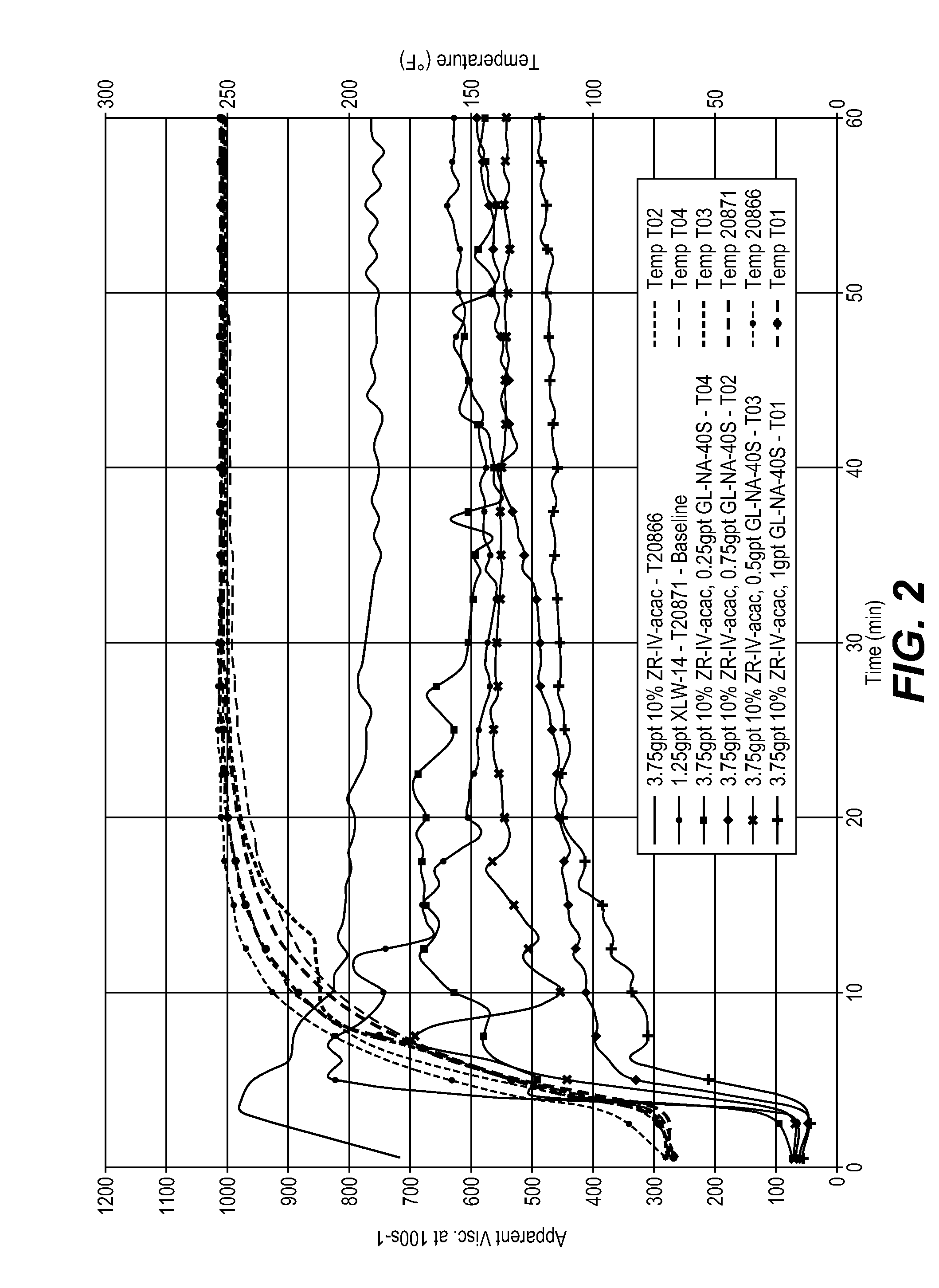
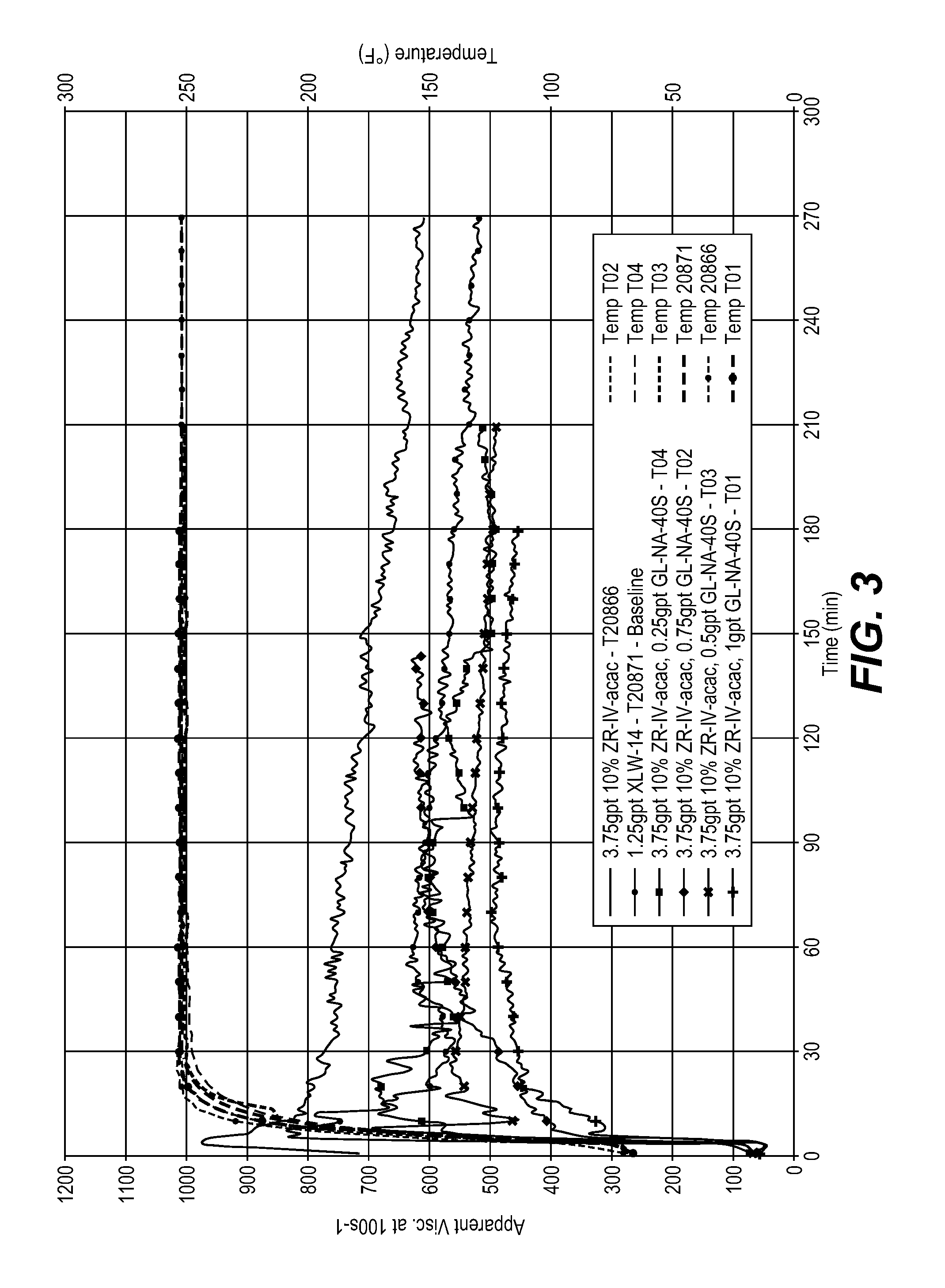
[0050]To the base fluid of Example 1 was added either ZR-IV-acac or XLW-14 and optionally glutamic acid-N,N-diacetic acid tetrasodium salt, 38% aqueous (Dissolvine GL-38-S, available from Akzo Nobel Polymer Chemicals, Amsterdam, Netherlands). FIGS. 2 and 3 show the results for crosslink delay with no high shear period. As demonstrated, the fluid with 0.25 gpt GL-NA-40S showed a similar delay time to the baseline fluid with XLW-14. The fluid with 0.25 gpt GL-NA-40S also showed comparable fluid stability performance to the baseline fluid with XLW-14. When the concentration of GL-NA-40S was higher than 0.5 gpt GL-NA-40S the fluid had a 30 minute delay in reaching peak viscosity. In all tests with the GL-NA-40S product the initial “peak” viscosity was lower than the “peak” viscosity obtained with the XLW-14 crosslinker.

example 3

[0051]FIG. 4 shows the Fann 50 results of the fluid at 250° F. with a 3 minute initial high shear of 450 s−1. FIG. 4 demonstrates that a concentration of 1.25 gpt GL-NA-40S showed slightly less initial “peak” viscosity but better stability than the XLW-14 crosslinker. Further, FIG. 4 shows that a minimum loading of 0.5 gpt GL-NA-40S was needed to show comparable fluid stability performance to the fluid with 1.25 gpt XLW-14 under the same conditions. As the concentration of the GL-NA-40S was increased from 0.5 to 1.25 gpt the fluid stability improved and initial “peak” viscosity increased. FIG. 4 does demonstrate that the concentration of the GL-NA-40S needed for optimization of fluid formulation varied depending on the high shear to which the fluid was exposed. The initial “peak” viscosity of all samples containing GL-NA-40S was lower than the “peak” viscosity obtained with the XLW-14 crosslinker.


PUM


Abstract

Crosslinking of a crosslinkable viscosifying agent and a crosslinking agent may be delayed in a well treatment fluid by incorporated within the fluid a glutamic-N,N-diacetic acid salt, such as a glutamic-N,N-diacetic acid sodium salt like tetrasodium glutamate diacetate. The crosslinking agent may be a zirconium containing crosslinking agent like zirconium (IV) acetyl acetonate. The viscosifying agent may be guar or a guar derivative such as carboxyalkyl guars and hydroxyalkylated guars like carboxymethyl guar, hydroxypropyl guar, hydroxyethyl guar, hydroxybutyl guar and carboxymethylhydroxypropyl guar.

Description

FIELD OF THE INVENTION[0001]The invention relates to a method of delaying crosslinking during a well treatment operation by introducing into the wellbore a fluid containing a glutamic acid-N,N-diacetic acid salt.BACKGROUND OF THE INVENTION[0002]Hydraulic fracturing is the process of enhancing oil and / or gas production from producing wells or enhancing the injection of water or other fluids into injection wells. Typically, a fracturing fluid is injected into the well, passing down the tubulars to the subterranean formation penetrated by the wellbore. The fluid is then pumped at rates and pressures that exceed the confining stresses in the formation, causing the formation to fail by inducing a fracture. This fracture originates at the wellbore and extends in opposite directions away from the wellbore. As more fluid is injected, the length, width and height of the fracture continue to extend. At a point, the width increases so that propping agents are added to the fluid and carried to ...

Claims


Application Information

Patent Timeline
IPC IPC(8): C09K8/62
CPCC09K8/887C09K8/685E21B43/26
Inventor GUPTA, D. V. SATYANARAYANACAWIEZEL, KAY ELAINE
Owner BAKER HUGHES INC
Why Eureka
Eureka Blog
Learn More