Method and Apparatus for Electrically Locating a Fault in a Cable

a technology of fault detection and cable, applied in electrical testing, instruments, electric digital data processing, etc., can solve the problems of interference signals, masking or falsifying small-amplitude reflection signals, and difficult measurement, so as to improve the effect of cable fault detection

Inactive Publication Date: 2013-08-08
HAGENUK KMT KABELMESSTECHN
View PDF3 Cites 18 Cited by
  • Summary
  • Abstract
  • Description
  • Claims
  • Application Information

AI Technical Summary

Benefits of technology

[0015]The inventive method makes it possible to locate a cable fault in a cable by using the resonance characteristics of the cable, and particularly the portion of cable between the cable fault and the first cable end at which the testing apparatus is connected.
[0052]In order to be able to inform the user of the inventive method and apparatus regarding the location of the cable fault, without requiring the user to have extensive experience or knowledge in this field, and without requiring additional effort by the user, the frequency analysis may further include an automatic detection of relevant signal maxima. A simple determination of the (local) maxima can be carried out, for example, by comparing a local signal value with the respective neighboring data points to the right and to the left of the signal value of interest. However, in a further preferred particular embodiment, the automatic detection of a relevant maximum can be carried out in connection with an interval width and / or a threshold value for evaluating the signal value. Thereby, so-called “parasitic” maxima and unresolved maxima can be recognized and cleaned-up, i.e. filtered out or excluded from the useful signal data. The “parasitic maxima” can especially arise due to broadband noise and / or superimposed interference signals, which are formed, for example by arising inhomogeneities of the cable impedance.
[0053]In order to exclude interference effects and parasitic maxima, and to improve the signal quality of the frequency spectrum, the automatic detection in a particular embodiment may especially comprise applying a filter with variable boundary frequency on the frequency spectrum. Thereby, that can further comprise a frequency transformation of the frequency spectrum with subsequent multiplication by a variable window function, and final transformation back into a “cleaned” or filtered frequency spectrum. Then the relevant maxima are determined in this cleaned or filtered frequency spectrum.
[0054]Furthermore, in a particular embodiment of the invention, in the use of the filter with variable boundary frequency, a relevant maximum or several relevant maxima can be shifted. Thereby the resolving of the maxima can be improved.
[0059]According to an additional embodiment, the measurement of the imposed or induced oscillation can be carried out in the time domain, and then transformed into the frequency domain by a suitable transformation. Thereby, finally, the locating of the cable fault can be improved or even made possible in the first place.

Problems solved by technology

Thus, this measurement is made more difficult by interference signals that are present, for example interference signals that have been coupled into the cable from the surrounding environment.
Such interference signals tend to mask or falsify the small-amplitude reflection signals of interest.
Furthermore, the evaluation of the measured data is also made more difficult because multiple reflections typically arise in the cable, due to a multiplicity of reflection points, e.g. points of variation of the characteristic wave impedance in the cable being tested.

Method used


Image

  • Method and Apparatus for Electrically Locating a Fault in a Cable
  • Method and Apparatus for Electrically Locating a Fault in a Cable
  • Method and Apparatus for Electrically Locating a Fault in a Cable

Examples


Embodiment Construction

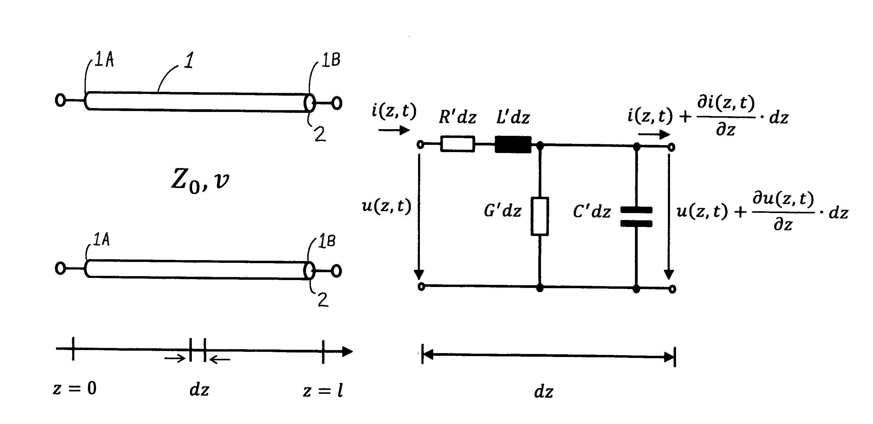
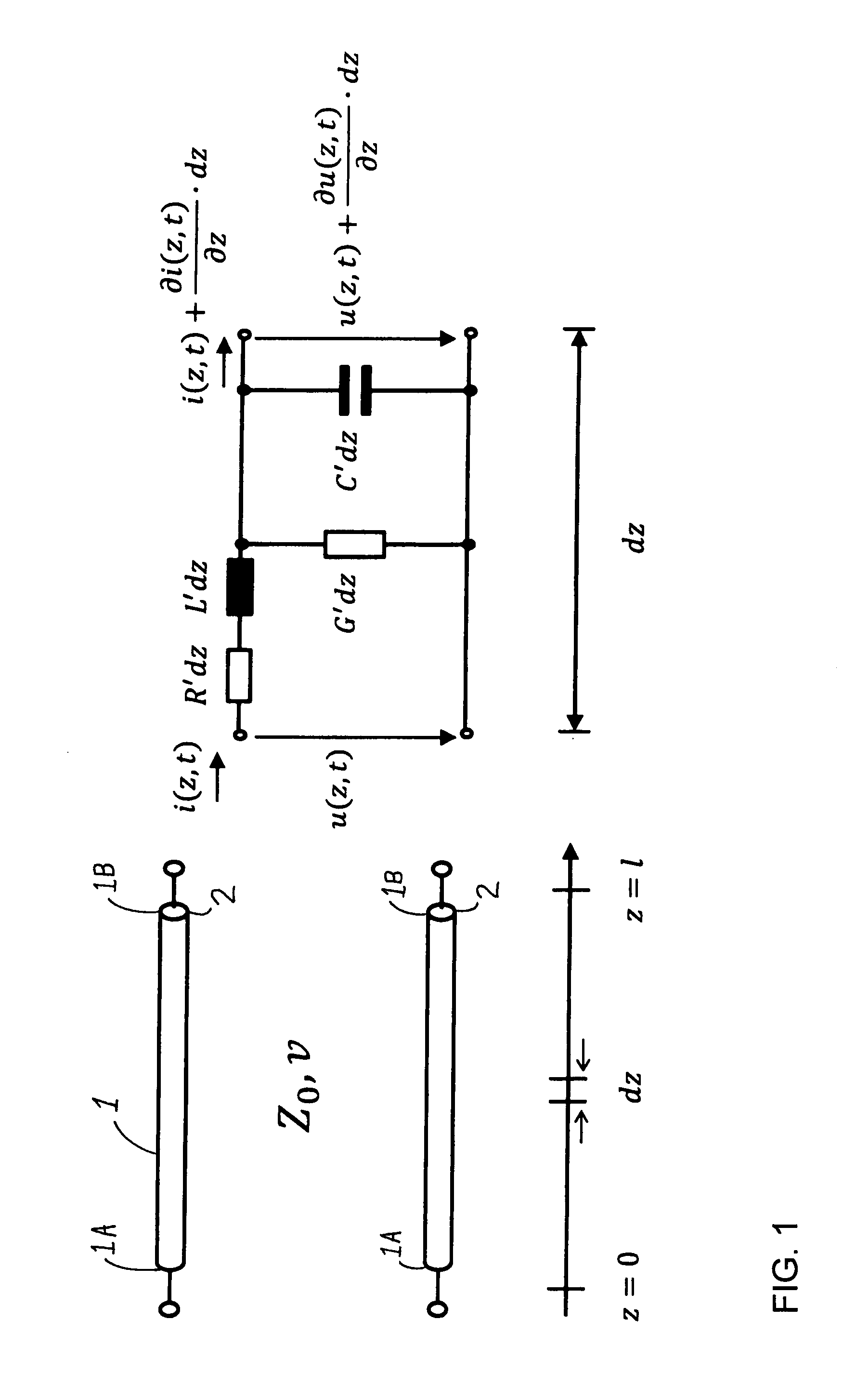
[0067]In the schematic diagram of FIG. 1, a test cable 1, i.e. a cable that is to be tested for locating a cable fault 2 therein, is represented physically extending from the physical location or length z=0 at a first cable end 1A of the test cable 1, to the physical location or length z=l at a second cable end 1B of the test cable 1. This second cable end 1B is not a second free end of the total length of the cable, but rather corresponds to a cable fault location of the cable fault 2, because at this cable fault 2 the cable is effectively electrically terminated by a short circuit due to breakdown of the cable insulation by an electrical arc that is ignited during the testing. The purpose of the testing is ultimately to determine the physical length of the cable 1 from the first cable end 1A to the second cable end 1B, i.e. the location of the cable fault 2 along the length of the cable. With that information, it is a simple matter to trace back along the cable from the first cabl...


PUM


Abstract

In order to locate a cable fault in a cable, a testing apparatus applies a test signal to the cable so as to induce an electrical oscillation. The testing apparatus includes a voltage source that generates the test signal, which e.g. ignites an electrical arc at the cable fault or applies a voltage surge to the cable, to cause the electrical oscillation. The apparatus further includes a measured signal evaluation device to measure the resulting oscillations in the time domain or the frequency domain, and carry out a spectral analysis in the frequency domain, so as to automatically determine the location of the fault preferably from the total phase rotation of the signal, the phase rotation of the reflection at the first cable end, the phase rotation of the reflection at the cable fault, and the imaginary part of the propagation constant of the signal in the cable.

Description

PRIORITY CLAIM[0001]This application is based on and claims the priority under 35 USC 119 of German Patent Applications DE 10 2012 002 439.8 filed on Feb. 6, 2012, and DE 10 2012 006 332.6 filed on Mar. 28, 2012, the entire disclosures of which are incorporated herein by reference.FIELD OF THE INVENTION[0002]The invention relates to a method and an apparatus for electrically testing a cable with a testing apparatus for locating a cable fault in the cable under test. The testing apparatus and the test cable together form an electrical system.BACKGROUND INFORMATION[0003]The electrical testing of cable systems of large expanse or of high complexity for locating cable faults in these cable systems is well known in the prior art, and is the subject matter of many patent applications. For example, see the German Patent Applications DE 22 010 24 A, DE 196 172 43 A1, DE 100 194 30 A1, and DE 24 550 07 A1. The established methods of locating a cable fault in a cable system typically use the ...

Claims


Application Information

Patent Timeline
Patent Type & Authority Applications(United States)
IPC IPC(8): G01R31/08G01R23/16
CPCG01R23/16G01R31/11G01R31/083G01R31/088
Inventor SCHEUSCHNER, SVENHIRTE, MATTHIASPETZOLD, JOERGGEBHARDT, THOMAS
Owner HAGENUK KMT KABELMESSTECHN
Why Eureka
Try Eureka