Oil mist separator

a technology of oil mist separator and separator, which is applied in the field of separator to achieve the effect of enhancing the performance of oil mist separation from blow-by gas

Active Publication Date: 2013-08-15
TOKYO ROKI
View PDF3 Cites 16 Cited by
  • Summary
  • Abstract
  • Description
  • Claims
  • Application Information

AI Technical Summary

Benefits of technology

[0008]According to the present invention, the performance f

Problems solved by technology

However, this blow-by ga

Method used


Image

  • Oil mist separator
  • Oil mist separator
  • Oil mist separator

Examples


Embodiment Construction

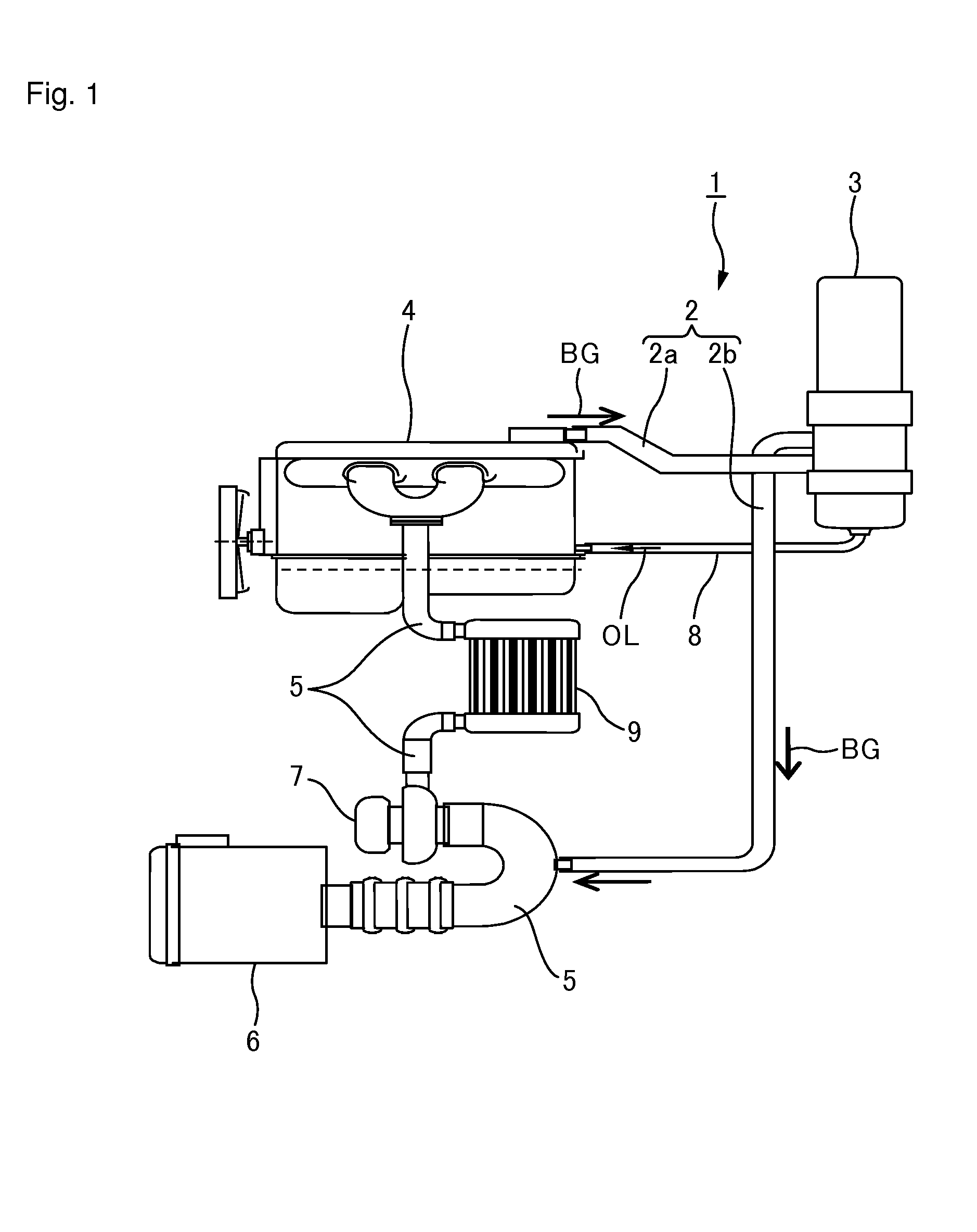
[0041]An embodiment of the present invention is described below with reference to the drawings. Here, an explanation is given on a closed crankcase ventilation system (hereinafter, referred to as a ventilation system).

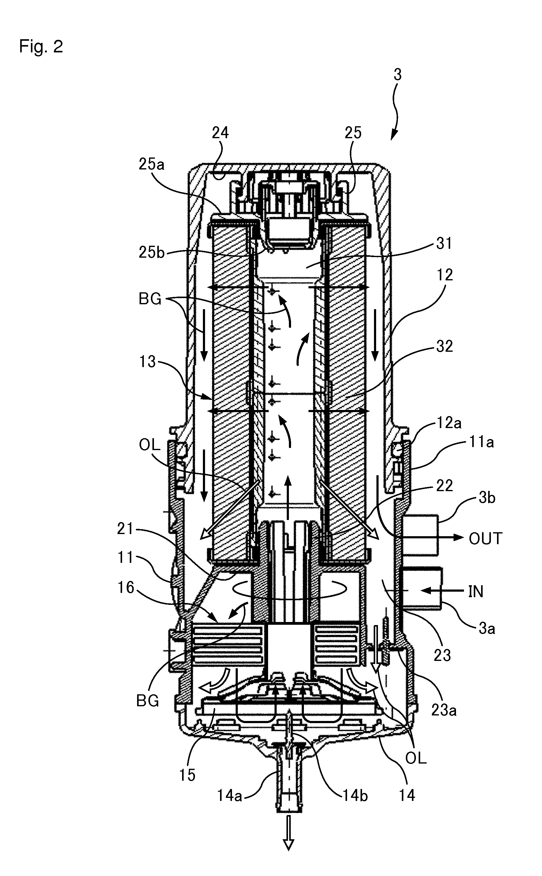
[0042]As shown in FIG. 1, a ventilation system 1 includes a breather pipe 2 and an oil separator unit 3. The breather pipe 2 partitions a returning channel for returning blow-by gas BG (oil-containing gas) discharged from a crankcase of an engine 4 to an air inlet side channel 5 that is in communication with the engine 4. The breather pipe 2 of the present embodiment returns the blow-by gas BG to a part of the air inlet side channel 5, at a position connecting an air filter 6 and a turbocharger 7. The oil separator unit 3 is provided halfway along the breather pipe 2, and separates and collects oil OL from the blow-by gas BG and returns the oil to the engine 4.

[0043]With this ventilation system 1, the blow-by gas GB discharged from the engine 4 flows into the oil separ...


PUM

PropertyMeasurementUnit
Flow rateaaaaaaaaaa
Widthaaaaaaaaaa

Abstract

[Problem to be Solved]
To enhance the performance for separation of oil mist from blow-by gas.
[Solution]
A filter element 13 which is to be attached to an oil separator unit 3 includes a core 31. This core is a double tube having an internal cylindrical member 34 and an external cylindrical member 35, and a space between the internal cylindrical member and the external cylindrical member is used as a separation chamber 36. An injection hole 39 for injecting blow-by gas while increasing its flow velocity is provided in the internal cylindrical member. A surface which is an inner wall surface of the external cylindrical member and which faces the injection hole is a spraying surface onto which the blow-by gas injected from the injection hole is sprayed. Moreover, an opening for oil discharge from which oil OL condensed on the spraying surface is discharged, and an opening for discharge from which the blow-by gas from which oil mist has been separated is discharged are provided in the core.

Description

TECHNICAL FIELD[0001]The present invention relates to a separator for separating oil mist from oil-containing gas containing oil mist.BACKGROUND ART[0002]With an engine of a vehicle and the like, blow-by gas is emitted from a combustion chamber toward the inside of a crankcase through a gap between a piston and a cylinder. This blow-by gas is an unburned mixture, and is thus returned to the engine. However, this blow-by gas also contains oil mist. Accordingly, at the time of returning the blow-by gas to the engine, the oil mist is separated from the blow-by gas by a ventilator.[0003]For example, a device described in PTL 1 accelerates the flow of blow-by gas by a nozzle, and injects the blow-by gas against a collision wall opposite the nozzle. This collision wall is covered with a textile or non-woven cloth, and is structured to absorb the oil mist.CITATION LISTPatent Literature[0004][Patent Literature 1] Japanese translation of PCT International application No. 2009-539013SUMMARY O...

Claims


Application Information

Patent Timeline
IPC IPC(8): F01M13/04
CPCB01D46/003B01D46/0043B01D46/2411B01D2265/06F01M2013/0488F01M2013/0072F01M2013/0427F01M2013/0438F01M13/04
Inventor WADA, MASAYAISHIDA, KOSAKUSHIRAKURA, KAZUKIENDO, YUTANAKAMURA, YOSHITAKATANAKA, KAZUOKUROSAWA, TAKATSUGUTAKASHIMA, JUN
Owner TOKYO ROKI
Why Eureka
Try Eureka