
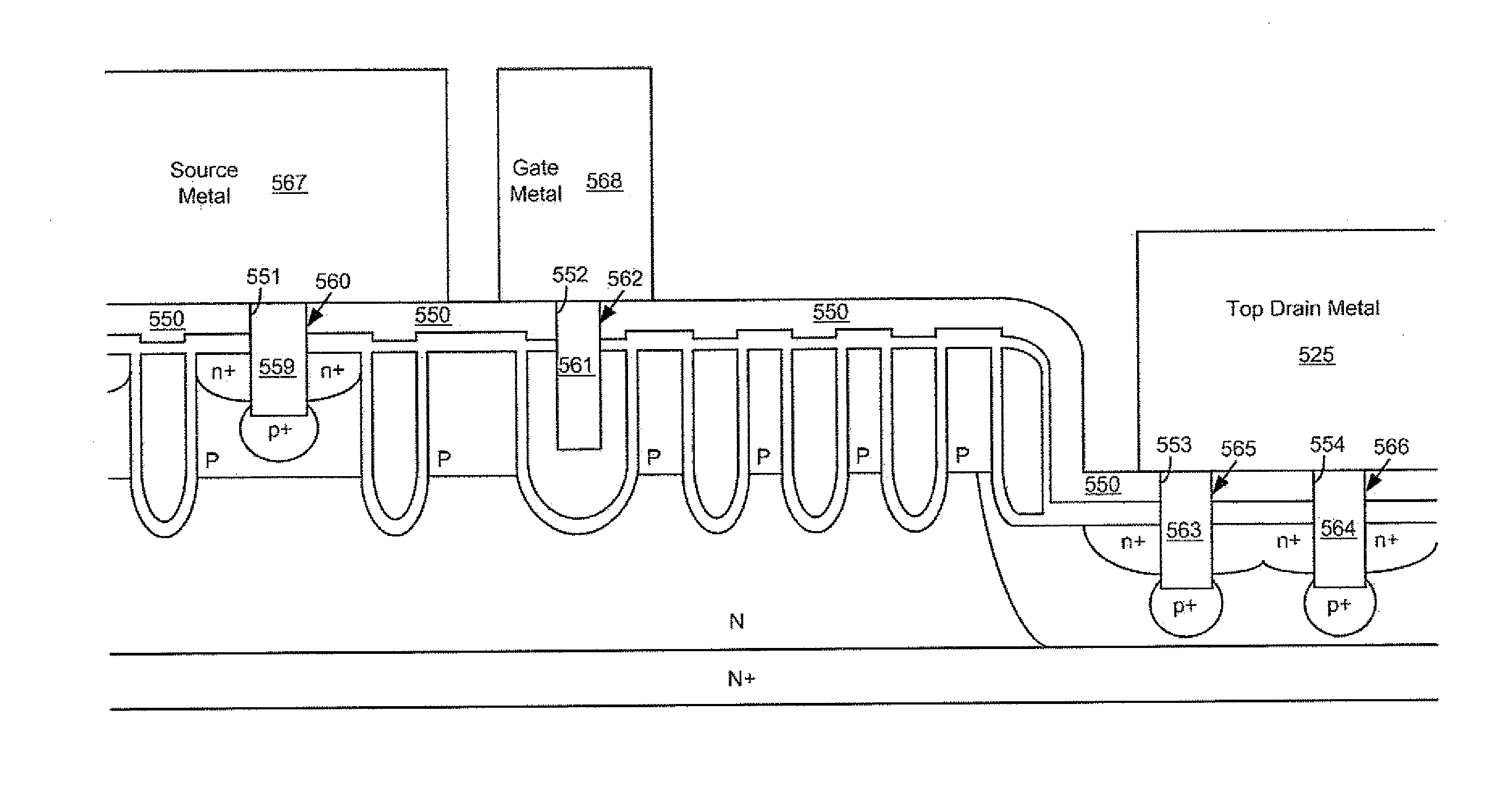
Trench mosfet having a top side drain

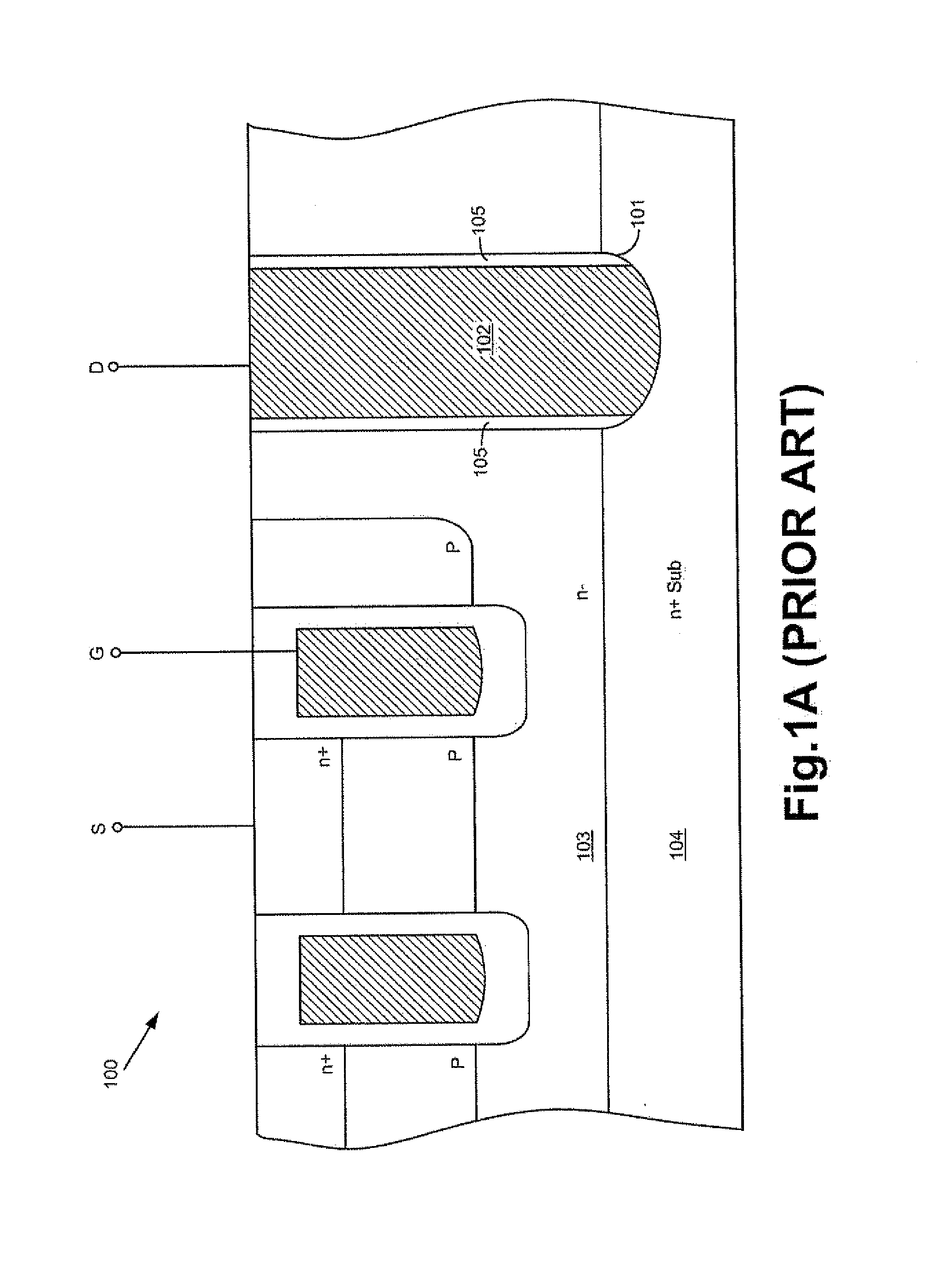
a top side drain and sinker trench technology, applied in the field of cell structure, can solve the problems of complex and not cost effective process for forming the deep sinker trench b>101/b> and the conductive material b>102/b>, and achieve the effect of reducing the concentration of doping, reducing the amount of doping, and increasing the junction depth

Active Publication Date: 2013-08-15
FORCE MOS TECH CO LTD
View PDF11 Cites 43 Cited by
  • Summary
  • Abstract
  • Description
  • Claims
  • Application Information

AI Technical Summary

Benefits of technology

The present invention provides a trench MOSFET with a top side drain and a method for manufacturing it. The technical effects of the invention include the following: no additional mask and no additional deep trench are required, the trenched drain contacts are formed simultaneously when a gate contact and a source-body contact are formed, the back drain metal has a lower resistivity than the substrate, the BV sustaining area can be formed by multiple trenched floating gates or a metal field plate, the source region can be formed by lateral or vertical diffusion, the source metal, gate metal, and top drain metal can be implemented by using Al alloys or Ti / Ni / Ag or Ti / Ni for flip chip packaging, a sinker region heavily doped with the first conductivity type can be formed to further reduce Rds, and the method for manufacturing the trench MOSFET is efficient and effective.

Problems solved by technology

However, the process to form the deep sinker trench 101 and the conductive material 102 is complicated and not cost effective.
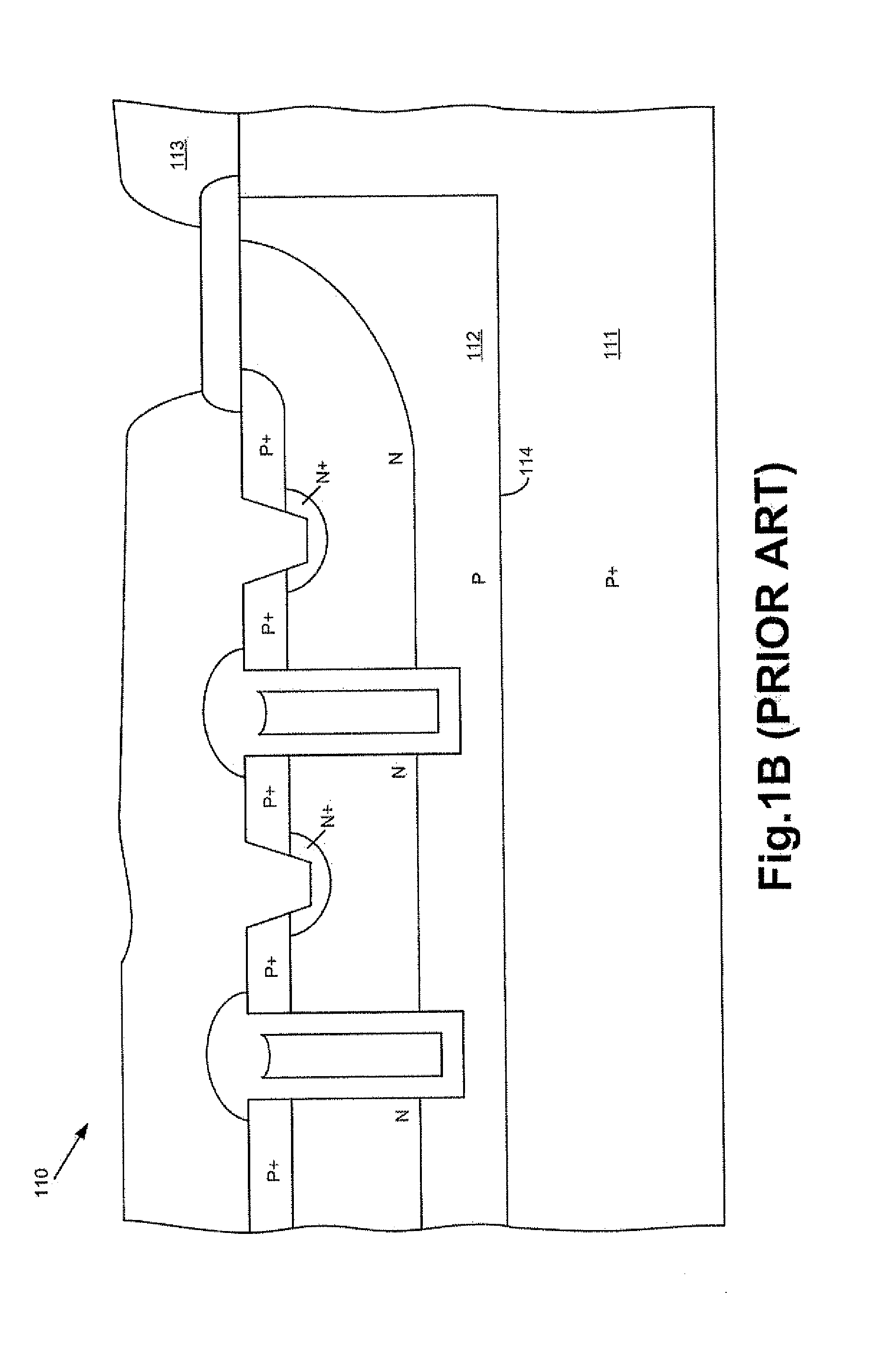
The trench MOSFET 110 is also formed through a complicated and not cost effective process.

Method used


Image

  • Trench mosfet having a top side drain
  • Trench mosfet having a top side drain
  • Trench mosfet having a top side drain

Examples


Embodiment Construction

[0029]In the following Detailed Description, reference is made to the accompanying drawings, which forms a part thereof, and in which is shown by way of illustration specific embodiments in which the invention may be practiced. In this regard, directional terminology, such as “top”, “bottom”, “front”, “back”, etc., is used with reference to the orientation of the Figure(s) being described. Because components of embodiments can be positioned in a number of different orientations, the directional terminology is used for purpose of illustration and is in no way limiting. It is to be understood that other embodiments may be utilized and structural or logical changes may be make without departing from the scope of the present invention. The following detailed description, therefore, is not to be taken in a limiting sense, and the scope of the present invention is defined by the appended claims. It is to be understood that the features of the various exemplary embodiments described herein...


PUM


Abstract

This invention discloses a trench MOSFET comprising a top side drain region in a wide trench in a termination area besides a BV sustaining area, wherein said top side drain comprises a top drain metal connected to an epitaxial layer and a substrate through a plurality of trenched drain contacts, wherein the wide trench is formed simultaneously when a plurality of gate trenches are formed in an active area, and the trenched drain contacts are formed simultaneously when a trenched source-body contact is formed in the active area.

Description

FIELD OF THE INVENTION[0001]This invention relates generally to the cell structure, device configuration and fabrication process of semiconductor power devices. More particularly, this invention relates to a novel and improved cell structure, device configuration and improved fabrication process of semiconductor power device having a top side drain.BACKGROUND OF THE INVENTION[0002]Flip chip package relates to a chip scale package and makes mounting a chip on a circuit board or other electric interface very convenient by using one surface of the chip. For a trench MOSFET (Metal Oxide Semiconductor Field Effect Transistor), gate, source and drain metals for external connection should be placed on one surface of the trench MOSFET, and can be bonded with solder balls on their surfaces for flip chip packaging. Trench MOSFET having a top side drain can be integrated with integrated circuit for some applications and for package foot print reduction.[0003]Please refer to FIG. 1A for a prior...

Claims


Application Information

Patent Timeline
Patent Type & Authority Applications(United States)
IPC IPC(8): H01L29/78H01L21/336
CPCH01L29/78H01L29/407H01L2924/0002H01L29/41766H01L29/4236H01L29/66727H01L29/7809H01L29/7811H01L29/7813H01L29/0623H01L29/0661H01L29/0878H01L29/0882H01L29/66734H01L2924/00
Inventor HSIEH, FU-YUAN
Owner FORCE MOS TECH CO LTD
Learn More