Converter for HVDC transmission and reactive power compensation

a technology of power electronic converter and converter, applied in the direction of electric variable regulation, process and machine control, instruments, etc., can solve the problems of high fault current in the power electronic converter, and achieve the effect of low power dissipation, low cost and low cos

Inactive Publication Date: 2013-08-15
ALSTOM TECH LTD
View PDF7 Cites 71 Cited by
  • Summary
  • Abstract
  • Description
  • Claims
  • Application Information

AI Technical Summary

Benefits of technology

[0016]The provision of switching elements controlled in this manner minimises the current flowing into and out of the DC network during the occurrence of a fault in the DC network resulting in high fault current in the power electronic converter. This in turn allows isolation of the fault in the DC network at near zero current, which prevents the formation of a sustained power arc and allows the use of standard AC side circuit breakers instead of expensive, specialised DC circuit breakers.
[0060]The provision of the or each auxiliary current flow path not only allows the fault current to be shared between the primary and auxiliary current flow paths, but also improves the speed of operation when the or each auxiliary current flow path is formed with the help of mechanical switching.

Problems solved by technology

The provision of switching elements controlled in this manner minimises the current flowing into and out of the DC network during the occurrence of a fault in the DC network resulting in high fault current in the power electronic converter.

Method used


Image

  • Converter for HVDC transmission and reactive power compensation
  • Converter for HVDC transmission and reactive power compensation
  • Converter for HVDC transmission and reactive power compensation

Examples


first embodiment

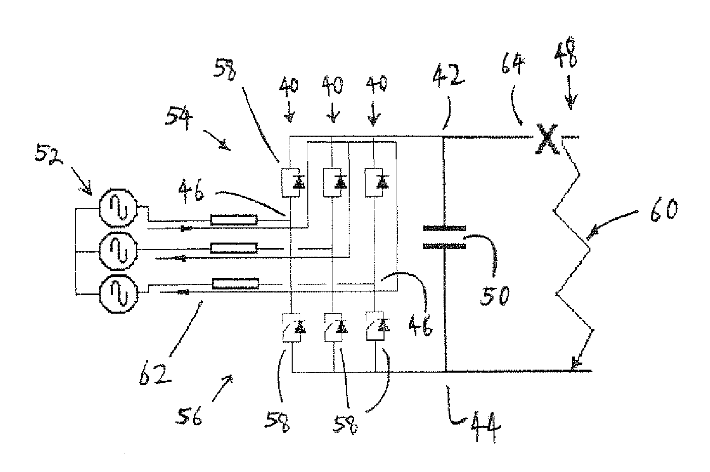
[0073]the power electronic converter comprises a plurality of converter limbs 40, as shown in FIGS. 4A to 4C. Each converter limb 40 includes first and second DC terminals 42, 44 and an AC terminal 46.

[0074]In use, the first DC terminal 42 of each converter limb 40 is connected to a positive terminal of a DC network 48 which carries a voltage of +VDC / 2, where VDC is the DC voltage range of the DC network 48 while the second DC terminal 44 of each converter limb 40 is connected to a negative terminal of a DC network 48 which carries a voltage of −VDC / 2. It is envisaged that in other embodiments, the first and second DC terminals of each converter limb may be respectively connected to negative and positive terminals of the DC network.

[0075]A DC link capacitor 50 is connected in series between the first and second DC terminals 42, 44 and in parallel with each converter limb 40.

[0076]In use, each AC terminal 46 is connected to a respective phase of a three-phase AC network 52. In other ...

second embodiment

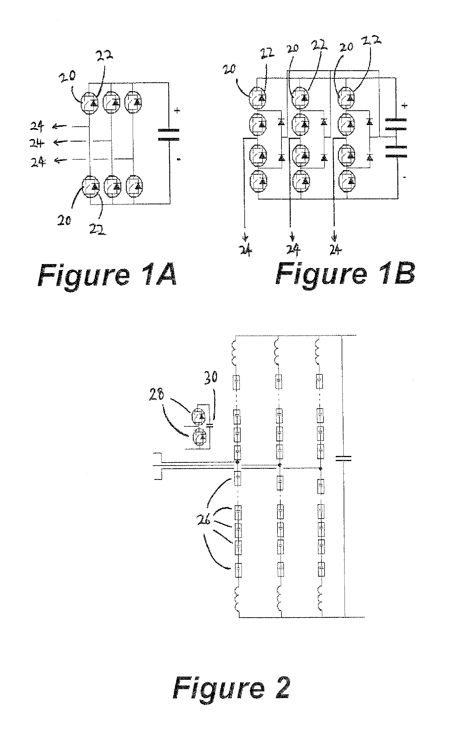
[0089]In the power electronic converter, the power electronic converter is exactly the same as the power electronic converter in FIGS. 4A, 4B and 4C except that each electronic block includes a chain-link converter. In such embodiments, the single chain-link converter in each electronic block may be replaced by a plurality of chain-link converters.

[0090]Each chain-link converter includes a chain of modules connected in series, each module including at least one pair of secondary switching elements connected in parallel with a capacitor. The secondary switching elements of each module are operable so that the chain of modules provides a stepped variable voltage source, and are switched at near to the fundamental frequency of the AC network.

[0091]The number of modules in each chain-link converter is determined by the required voltage rating of the voltage source converter.

[0092]In embodiments employing the use of one or more chain-link converters, each module may include a pair of sec...

third embodiment

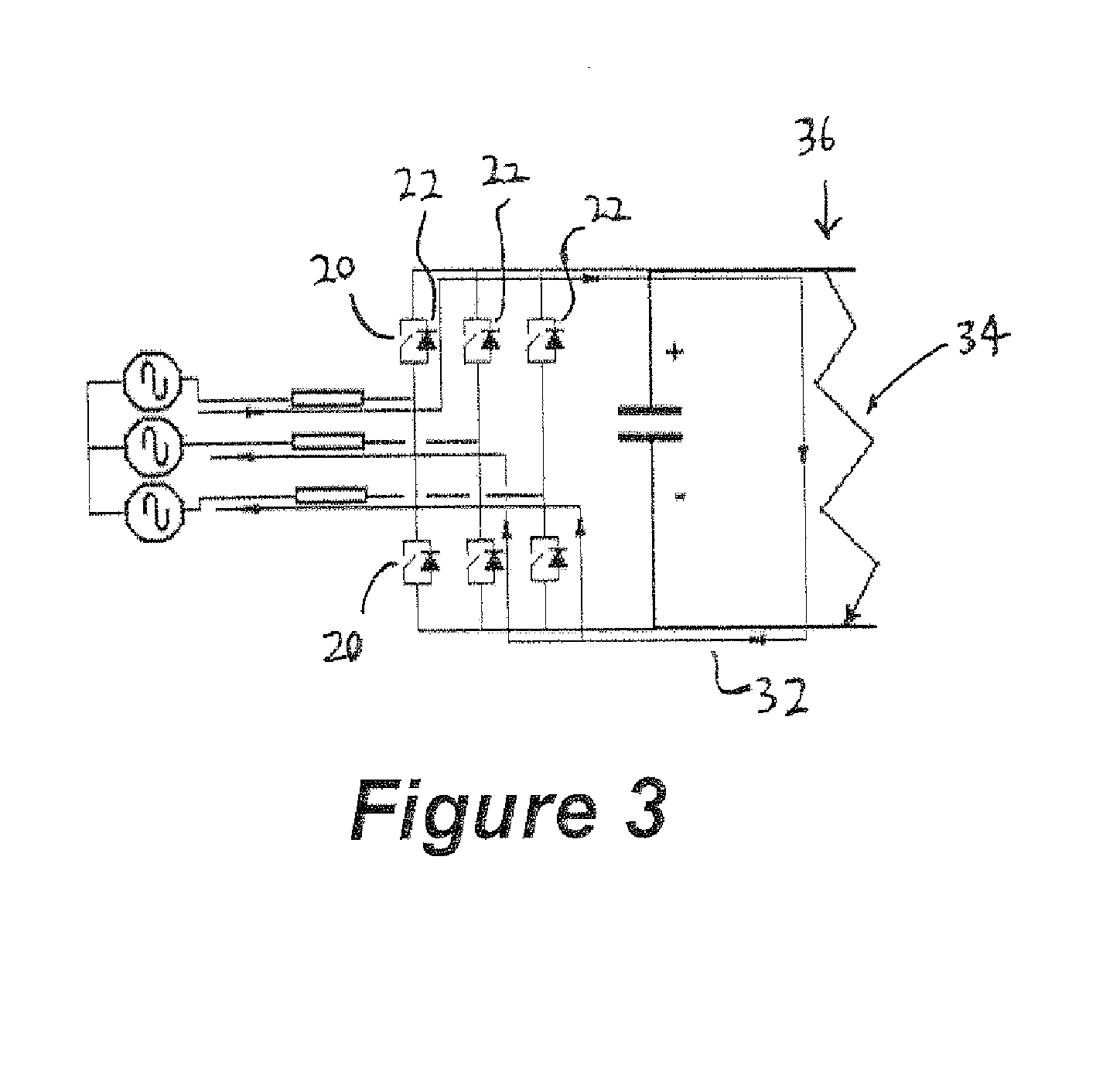
[0109]the power electronic converter is shown in FIG. 6. Each electronic block includes a primary switching element 58 connected in series with a chain-link converter 66. In FIG. 6, the primary switching element 58 of each of the first and second limb portions 54,56 is connected to the AC terminal 46, which is connected in use to an AC network 52, and the chain-link converter 66 of each of the first and second limb portions 54,56 is connected to the respective DC terminal 42,44, which is connected in use to a DC network 48.

[0110]The series connection between the primary switching element 58 and the chain-link converter of each of the first and second limb portions means that, in other embodiments, they may be connected in a reverse order between the AC terminal and the respective DC terminal.

[0111]It is also envisaged that in other embodiments, the arrangement and number of primary switching elements and chain-link converters in each electronic block of each limb portion may vary de...


PUM


Abstract

A power electronic converter for use in high voltage direct current power transmission and reactive power compensation comprises a plurality of switching elements interconnecting in use a DC network and one or more AC networks, the plurality of switching elements being controllable in use to facilitate power conversion between the AC and DC networks, wherein in use, the plurality of switching elements are controllable to form one or more short circuits within the power electronic converter so as to define one or more primary current flow paths, the or each primary current flow path including a respective one of the AC networks and the power electronic converter and bypassing the DC network.

Description

BACKGROUND OF THE INVENTION[0001]This invention relates to a power electronic converter for use in high voltage direct current (HVDC) power transmission and reactive power compensation.[0002]In power transmission networks alternating current (AC) power is typically converted to direct current (DC) power for transmission via overhead lines and / or undersea cables. This conversion removes the need to compensate for the AC capacitive load effects imposed by the transmission line or cable, and thereby reduces the cost per kilometer of the lines and / or cables. Conversion from AC to DC thus becomes cost-effective when power needs to be transmitted over a long distance.[0003]The conversion of AC to DC power is also utilized in power transmission networks where it is necessary to interconnect AC networks operating at different frequencies.[0004]In any such power transmission network, converters are required at each interface between AC and DC power to effect the required conversion, and one ...

Claims


Application Information

Patent Timeline
Patent Type & Authority Applications(United States)
IPC IPC(8): H02J3/36G05F1/70
CPCH02J3/36H02M7/483H02M2007/4835G05F1/70Y02E60/60H02M7/4835H02M1/0095H02M1/15H02M1/4208H02M7/04H02M7/145
Inventor TRAINER, DAVIDDAVIDSON, COLIN CHARNOCKOKAEME, NNAMDI
Owner ALSTOM TECH LTD
Why Eureka
Try Eureka