X-Ray Inspection using Wavelength-Shifting Fiber-Coupled Scintillation Detectors

a scintillation detector and wavelength-shifting technology, applied in the direction of radiation control devices, radiation particle tracking, optical radiation measurement, etc., can solve the problems of inherently low light collection efficiency of conventional backscatter detectors, noise limit of imaging systems, and different detection requirements of x-ray backscatter inspection systems

Active Publication Date: 2013-08-15
AMERICAN SCI & ENG INC
View PDF30 Cites 52 Cited by
  • Summary
  • Abstract
  • Description
  • Claims
  • Application Information

AI Technical Summary

Benefits of technology

[0017]In further embodiments of the invention, the optical waveguides in the foregoing detectors may be adapted for wavelength shifting of the scintillation light and, more particularly, may be wavelength-shifting optical fibers. The scintillation medium may include a lanthanide-doped barium mixed halide such as barium fluorochloride. The photo-detector may include a photomultiplier.
[0018]In yet further embodiments of the invention, the square of the thickn...

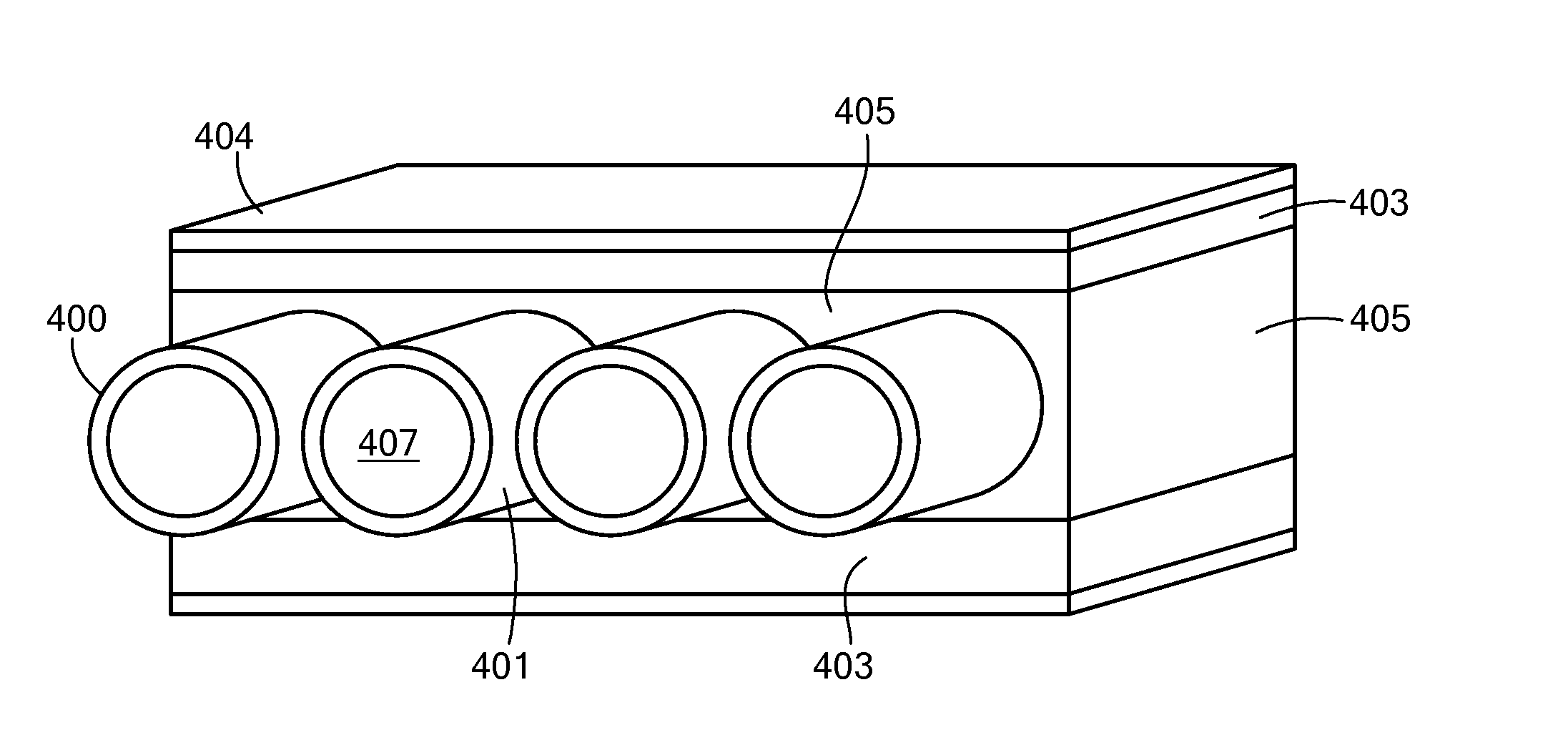
Problems solved by technology

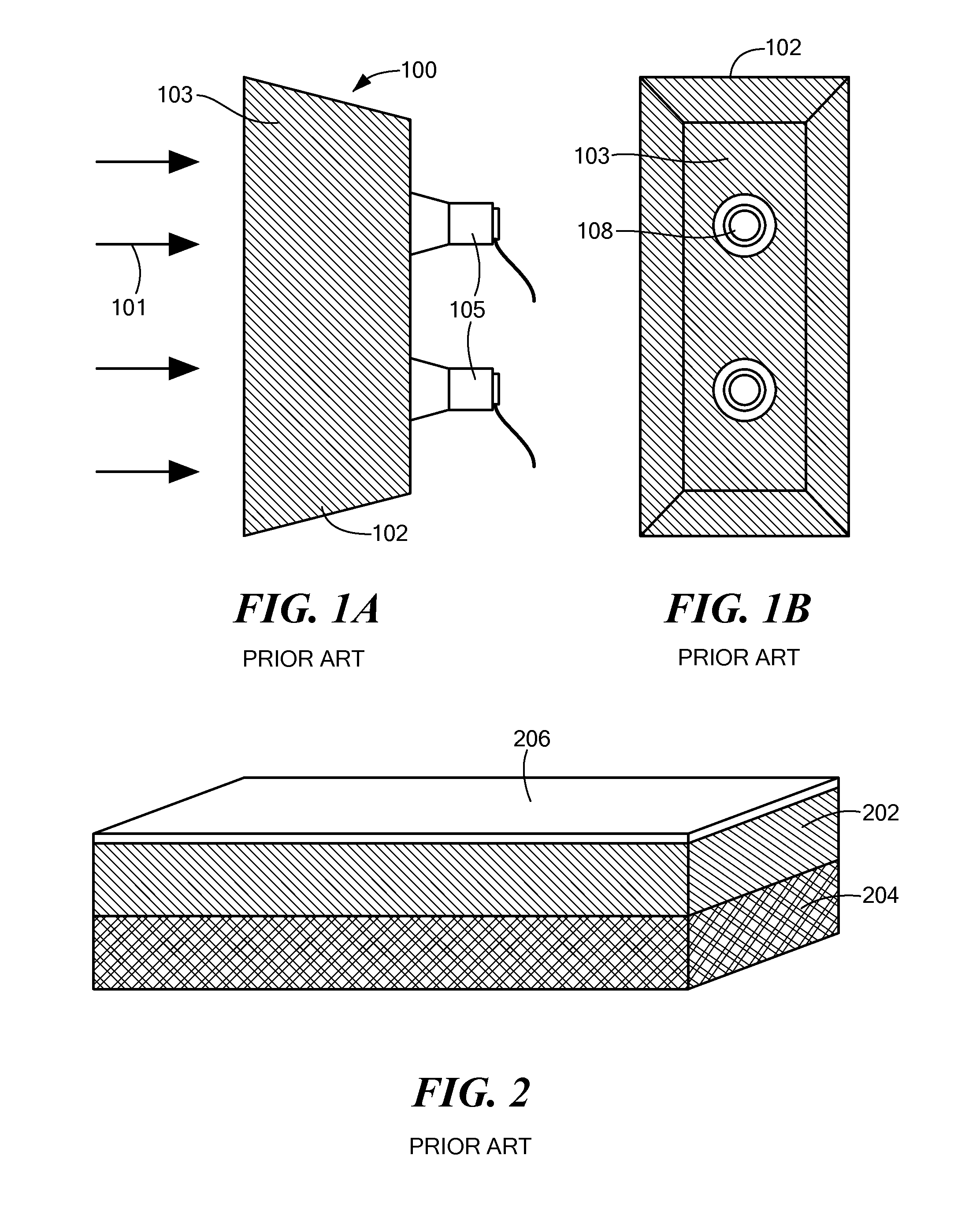
The detection requirements of x-ray backscatter inspection systems, however, are entirely different from the requirements addressed by existing fiber-coupled scintillation detectors.
One problem lies in that a fraction of the scintillation light originating within the screen is transmitted from the screen into the enclosed volume.
As a result, the light collection efficiency of the conventional backscatter detector is inherently low, with only a few percent of the generated scintillation light collected into the photo detectors.
The noise level at the quantum sink determines the noise limit of the imaging syst...

Method used


Image

  • X-Ray Inspection using Wavelength-Shifting Fiber-Coupled Scintillation Detectors
  • X-Ray Inspection using Wavelength-Shifting Fiber-Coupled Scintillation Detectors
  • X-Ray Inspection using Wavelength-Shifting Fiber-Coupled Scintillation Detectors

Examples


Embodiment Construction

[0012]In accordance with various embodiments of the present invention, systems and methods are provided that apply fiber-coupled scintillation detectors to problems in backscatter and transmission x-ray inspection.

[0013]For convenience of notation, a wavelength-shifted fiber-coupled scintillation detector may be referred to herein as an “Sc-WSF” detector.

[0014]In a first embodiment of the present invention, a detector of penetrating radiation is provided that has an unpixelated volume of scintillation medium for converting energy of incident penetrating radiation into scintillation light. The detector has multiple optical waveguides, aligned substantially parallel to each other over a scintillation light extraction region that is contiguous with the unpixelated volume of the scintillation medium, The optical waveguides guide light derived from the scintillation light to a photo-detector for detecting photons guided by the waveguides and for generating a detector signal.

[0015]In othe...


PUM


Abstract

A detector and methods for inspecting material on the basis of scintillator coupled by wavelength-shifting optical fiber to one or more photo-detectors, with a temporal integration of the photo-detector signal. An unpixelated volume of scintillation medium converts energy of incident penetrating radiation into scintillation light which is extracted from a scintillation light extraction region by a plurality of optical waveguides. This geometry provides for efficient and compact detectors, enabling hitherto unattainable geometries for backscatter detection and for energy discrimination of incident radiation. Additional energy-resolving transmission configurations are enabled as are skew- and misalignment compensation.

Description

[0001]The present application claims priority from U.S. Provisional Patent Applications, Ser. Nos. 61 / 598,521, and 61 / 598,576, both filed Feb. 14, 2012, and U.S. Provisional Patent Applications, Ser. No. 61 / 607,066, filed Mar. 6, 2012, all of which applications are incorporated by reference herein.TECHNICAL FIELD[0002]The present invention relates to fiber-coupled scintillation detectors and to methods of their manufacture, and to systems and methods of x-ray inspection employing fiber-coupled scintillation detectors for efficient detection of x-rays.BACKGROUND ART[0003]Fiber-coupled scintillation detectors of radiation and particles have been employed over the course of the past 30 years. In some cases, the scintillator is pixelated, consisting of discrete scintillator elements, and in other cases, other stratagems are employed (such as orthogonally crossed coupling fibers) in order to provide spatial resolution. Examples of fiber-coupled scintillation detectors are provided by U.S...

Claims


Application Information

Patent Timeline
IPC IPC(8): G01T1/20G01N23/20G01N23/06
CPCG01T1/2006G01N23/06G01V5/0025G01T5/08G01N23/20G01T1/2008G01T3/06G01T1/20181G01T1/20185G01V5/0016H01L27/146H01L27/14643H01L27/14658H01L27/14601G01T1/20G01T1/201G01T7/00
Inventor ARODZERO, ANATOLICALLERAME, JOSEPHDINCA, DAN-CRISTIANSUD, RAJENGRODZINS, LEEROMMEL, MARTINROTHSCHILD, PETERSCHUBERT, JEFFREY
Owner AMERICAN SCI & ENG INC
Why Eureka
Try Eureka