Eureka AIR delivers breakthrough ideas for toughest innovation challenges, trusted by R&D personnel around the world.

Method of manufacturing layered structure constituting all-solid-state battery, apparatus for manufacturing the same, and all-solid-state battery provided with layered structure

Active Publication Date: 2013-08-15
SINTOKOGIO LTD
View PDF3 Cites 9 Cited by
  • Summary
  • Abstract
  • Description
  • Claims
  • Application Information

AI Technical Summary

Benefits of technology

The invention is about a method of manufacturing an all-solid-state battery using a coating process. The method involves using a thin layered structure, which makes it difficult to separate and use the layers without damaging them, resulting in lower yields. The invention proposes a method to address this problem by using a carrier sheet with concavities and convexities that helps in forming the layers simultaneously. This reduces the cost of manufacturing and avoids the need for a separate sheet.

Problems solved by technology

So, there are problems, such as an oil leak.
Also, although the lithium ion battery has a record in that it has often been used as an electric source for a portable device such as a laptop computer, a mobile phone, etc., it has often been reported that the lithium ion battery has caused a fire or explosion.
However, the batteries manufactured by these methods have an insufficient binding force that works between adjacent layers, so that an interface resistance is likely to increase.
So, if the binding force that works between the adjacent layers is insufficient, a sufficient interfacial strength cannot be obtained.
For this reason, defects such as separation of the layers occurs, which defects are likely to lower the capacity of the batteries or to shorten the lives of the batteries.

Method used


Image

  • Method of manufacturing layered structure constituting all-solid-state battery, apparatus for manufacturing the same, and all-solid-state battery provided with layered structure
  • Method of manufacturing layered structure constituting all-solid-state battery, apparatus for manufacturing the same, and all-solid-state battery provided with layered structure
  • Method of manufacturing layered structure constituting all-solid-state battery, apparatus for manufacturing the same, and all-solid-state battery provided with layered structure

Examples


modified embodiment

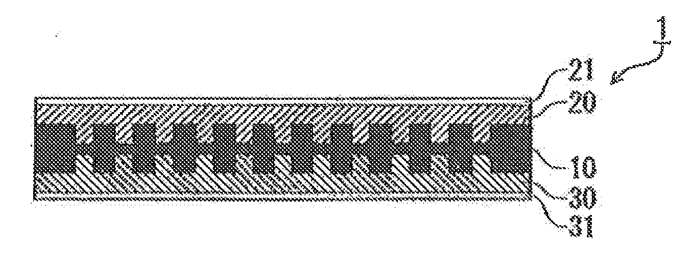
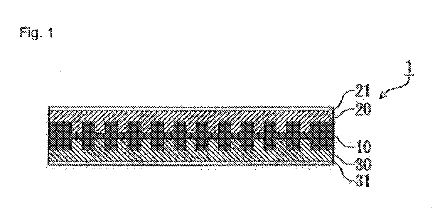
[0086]In the above embodiment the concavities and convexities were formed on both sides of the green sheet for a solid electrolyte 11. But the concavities and convexities can be formed on only one side of the green sheet for a solid electrolyte 11.

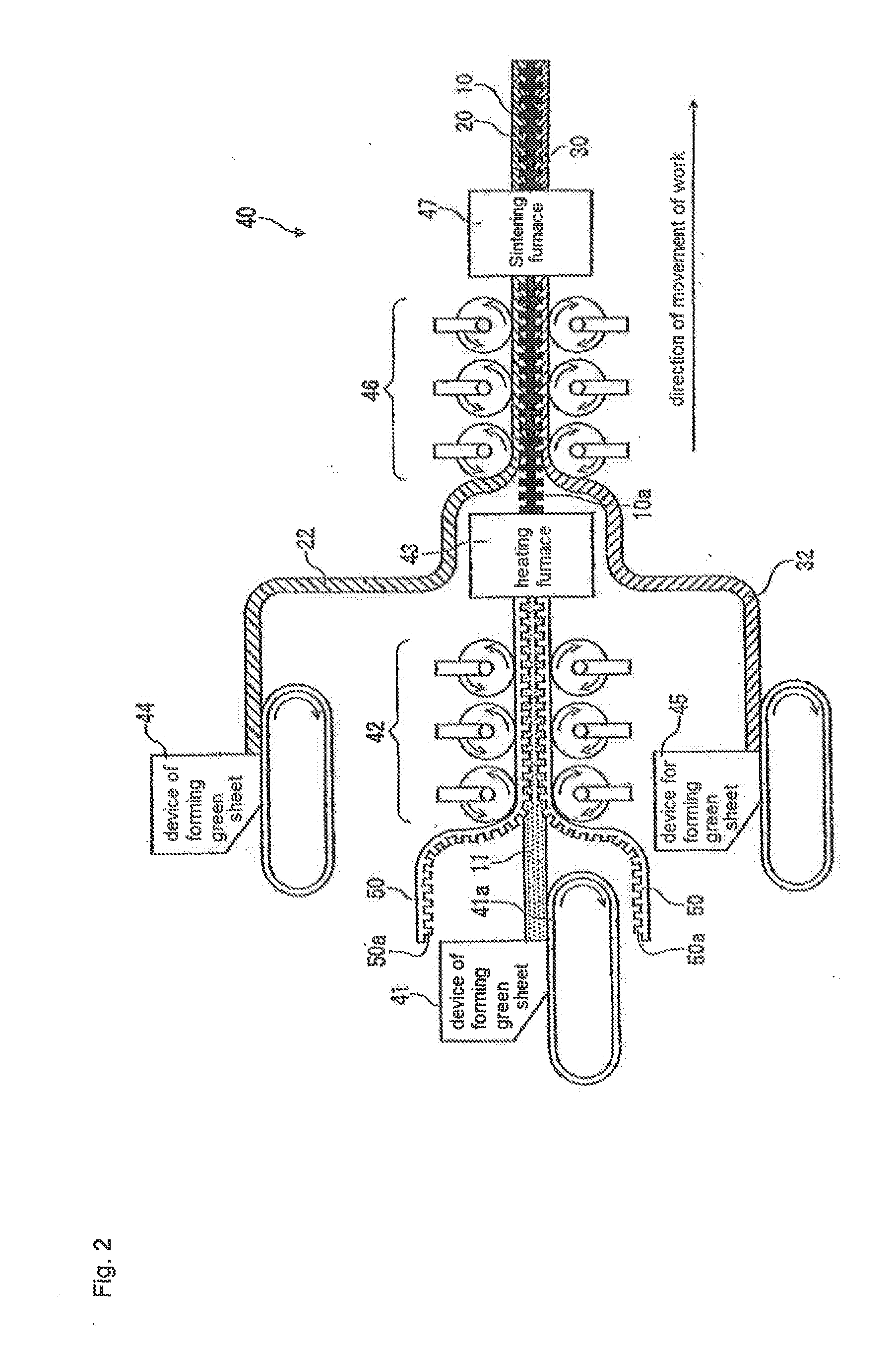
[0087]The green sheet for positive electrode active material 22 and the sheet member 50 that has the concavities and convexities formed on the surface are formed in one piece. Then by having the sheet member 50 disappear by heating the jointed body of the green sheet for positive electrode active material 22 and the sheet member 50 that is formed in one piece, the layered structure of the positive electrode active material layer 20 that has the concavities and convexities formed on the surface is formed. Similarly, the green sheet for negative electrode active material 32 and the sheet member 50 that has the concavo-convex shapes formed on the surface are formed in one piece. Then by having the sheet member 50 disappear by heating the join...

example 1

[0094]In the present example, the layered structure of a solid electrolyte layer was manufactured.

[0095]The particles of Li1.5Al0.5Ge1.5(PO4)3 that were previously vitrified are prepared as raw powder material for the solid electrolyte material. The particles were then mixed with an organic solvent and made into slurry.

[0096]Next, the slurry is cast by the doctor blade method and a green sheet for a solid electrolyte with a thickness of 500 μm was prepared. Then this green sheet for a solid electrolyte was formed into a circular shape having a diameter of 11.28 mm.

[0097]Then, a film of an organic compound having the concavities and convexities that were formed was prepared so that it had the same size as the green sheet for a solid electrolyte. This film of the organic compound was produced from polyvinyl alcohol, where after the polyvinyl alcohol had been dissolved in hot water and made a solvent, which was then applied to a die having a concavity and a convexity, it was heated, dr...

example 2

[0101]In the present embodiment the positive electrode active material layer and the negative electrode active material layer were manufactured.

[0102]For the materials that were used for the positive electrode active material layer and the negative electrode active material layer, crystal powder Li3V2 (PO4)3 that was prepared in advance was used. This raw powder material was mixed with an organic solvent and was prepared into slurry.

[0103]Next, the slurry was cast by the doctor blade method and a green sheet for positive electrode active material and a green sheet for negative electrode active material, each having a thickness of 1,000 μm, were manufactured. The green sheet for positive electrode active material and the green sheet for negative electrode active material were, thereafter, cut into sheets of a circular shape, each having a diameter of 11.28 mm.

[0104]By steps similar to those given in Example 1, the layered structure having the green sheet for positive electrode active...


PUM

PropertyMeasurementUnit
Structureaaaaaaaaaa
Electrical resistanceaaaaaaaaaa
Strengthaaaaaaaaaa

Abstract

The present invention provides a method of manufacturing a layered structure and an apparatus for manufacturing a layered structure where the layered structure comprises a solid electrolyte layer, a positive electrode active material layer, and a negative electrode active material layer, which together constitute an all-solid-state battery, enables the interfacial resistance to be lowered, enables the interfacial strength to be increased, enables an improved yield rate, and enables a low manufacturing cost.The layered structure that has concavities and convexities formed on the surface is manufactured by the method comprising steps of:forming a green sheet S111, where the green sheet for a solid electrolyte layer 11 is formed; forming concavities and convexities S112, where (1) the green sheet for a solid electrolyte layer 11 and (2) the sheet member 50 that is made from material that is caused to disappear when heated, and that has concavities and convexities, are formed in one piece, and the concavities and convexities are formed on the surface of the green sheet for a solid electrolyte layer 11; heating S113, where the sheet member 50 is caused to disappear by heating the green sheet for a solid electrolyte layer 11 and the sheet member 50 that are formed in one piece, and where the green sheet for a solid electrolyte layer 11 is sintered.

Description

FIELD OF THE INVENTION[0001]This invention is directed to a method of manufacturing a layered structure selected from a solid electrolyte layer, a positive electrode active material layer, and a negative electrode active material layer, that together constitute an all-solid-state battery, an apparatus for manufacturing a layered structure, and the all-solid-state battery provided with the layered structure.BACKGROUND ART[0002]Recently a social demand for an environment-friendly vehicle has increased so that development is in progress of a vehicle that is not driven by an internal-combustion engine that mainly uses conventional gasoline or light oil, but a so-called hybrid electric vehicle that is driven by a combination of the internal-combustion engine and an electric motor or an electric vehicle that is driven by the electric motor. Already some of these vehicles have been put into practical use and have been on sale.[0003]For the hybrid electric vehicle and the electric vehicle, ...

Claims


Application Information

Patent Timeline
IPC IPC(8): H01M4/04H01M50/463
CPCH01M2/1673Y10T29/49108H01M4/0471H01M4/139H01M4/405H01M4/58H01M4/5825H01M10/0404H01M10/0525H01M10/0562H01M10/0585Y02T10/7011Y02E60/122H01M4/04H01M4/0409Y10T29/53135H01M2/18Y02P70/50Y02E60/10H01M50/46H01M50/463Y02T10/70
Inventor NAGASAKA, MASAHIKONAKAJIMA, SHOGONOZAWA, TAKAYUKISUGINO, OSAMUMISHIMA, IKUTO
Owner SINTOKOGIO LTD
Why Eureka
Eureka Blog
Learn More