Diesel engine/gas turbine compound engine for a means of transport

Inactive Publication Date: 2013-08-22
AIRBUS OPERATIONS GMBH
View PDF6 Cites 21 Cited by
  • Summary
  • Abstract
  • Description
  • Claims
  • Application Information

AI Technical Summary

Benefits of technology

[0027]If part of the gas turbine is used as a turbocharger for the diesel engine, this part is decoupled from operation of the gas turbine by means of corresponding clutches and valves. Consequently, concurrent use of the diesel engine with the turbocharger and the remainder of the gas turbine is possible.
[0028]According to an exemplary embodiment, the gas turbine is serially connected in the manner of a classical multi-shaft engine, wherein the gas turbine comprises high-pressure and low-pressure turbines and high-pressure and low-pressure compressors, wherein the low-pressure compressor and the low-pressure turbine or the high-pressure compressor and the high-pressure turbine run on separate shafts. This provides an advantage in that low-pressure and high-pressure turbines can operate at different rotary speeds. Optionally, on a further, separate, shaft, a power turbine can be connected downstream. The separate shafts can be designed individually or can be combined in a hollow shaft. Th

Problems solved by technology

Said diesel technology is characterized by high efficiency; however, the engines are usually comparatively heavy.
In p

Method used


Image

  • Diesel engine/gas turbine compound engine for a means of transport
  • Diesel engine/gas turbine compound engine for a means of transport
  • Diesel engine/gas turbine compound engine for a means of transport

Examples


Embodiment Construction

[0045]The illustration in the figures is diagrammatic and not to scale. The same reference characters are used for identical or similar elements.

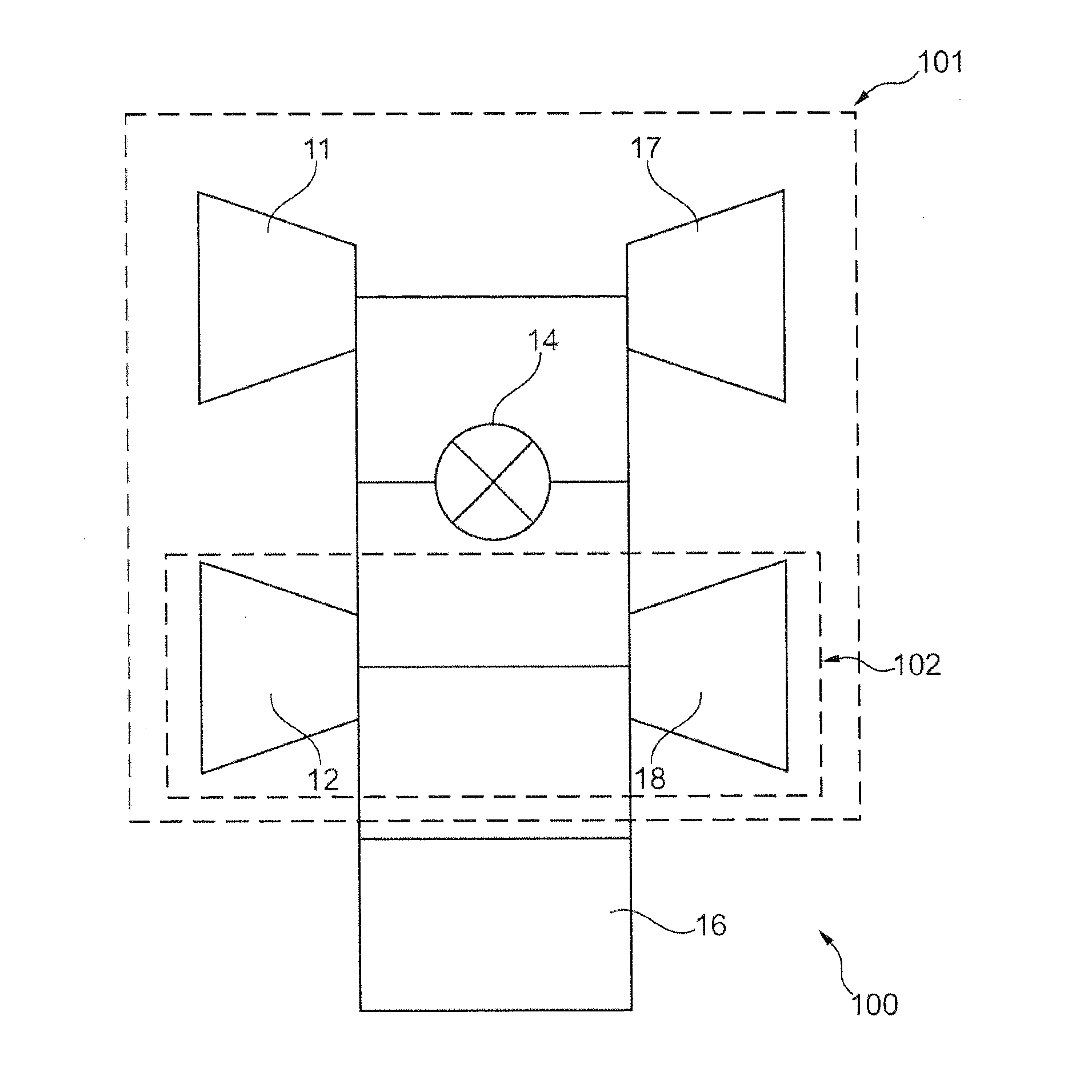
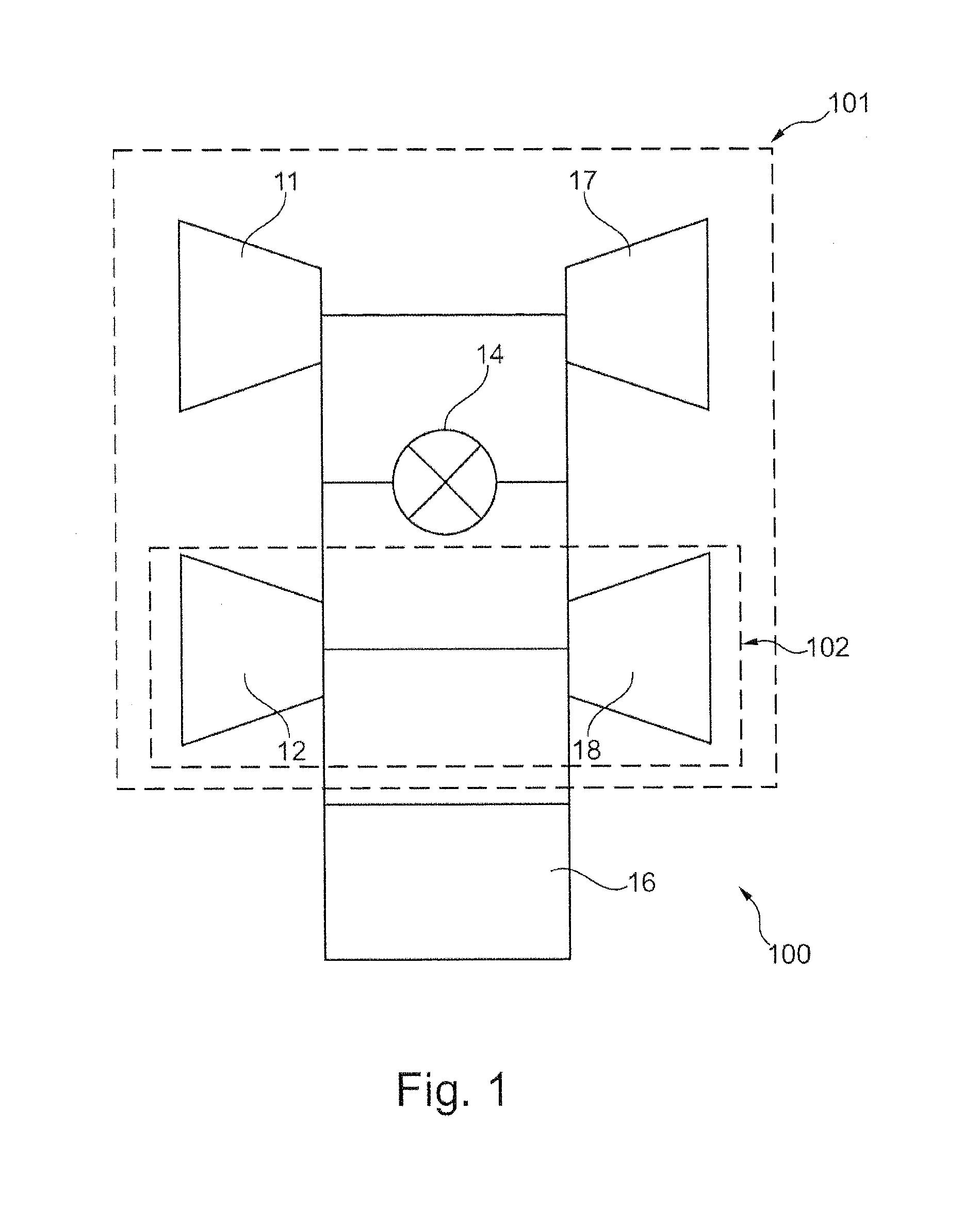
[0046]FIG. 1 diagrammatically shows a compound engine 100 comprising a gas turbine 101 and a diesel engine 16, wherein part of the gas turbine 101 can be used as a turbocharger 102 for the diesel engine 16. The combustion chamber 14 can be a shared combustion chamber for the compressors 11, 12 and the turbines 17, 18, or several combustion chambers can be used.

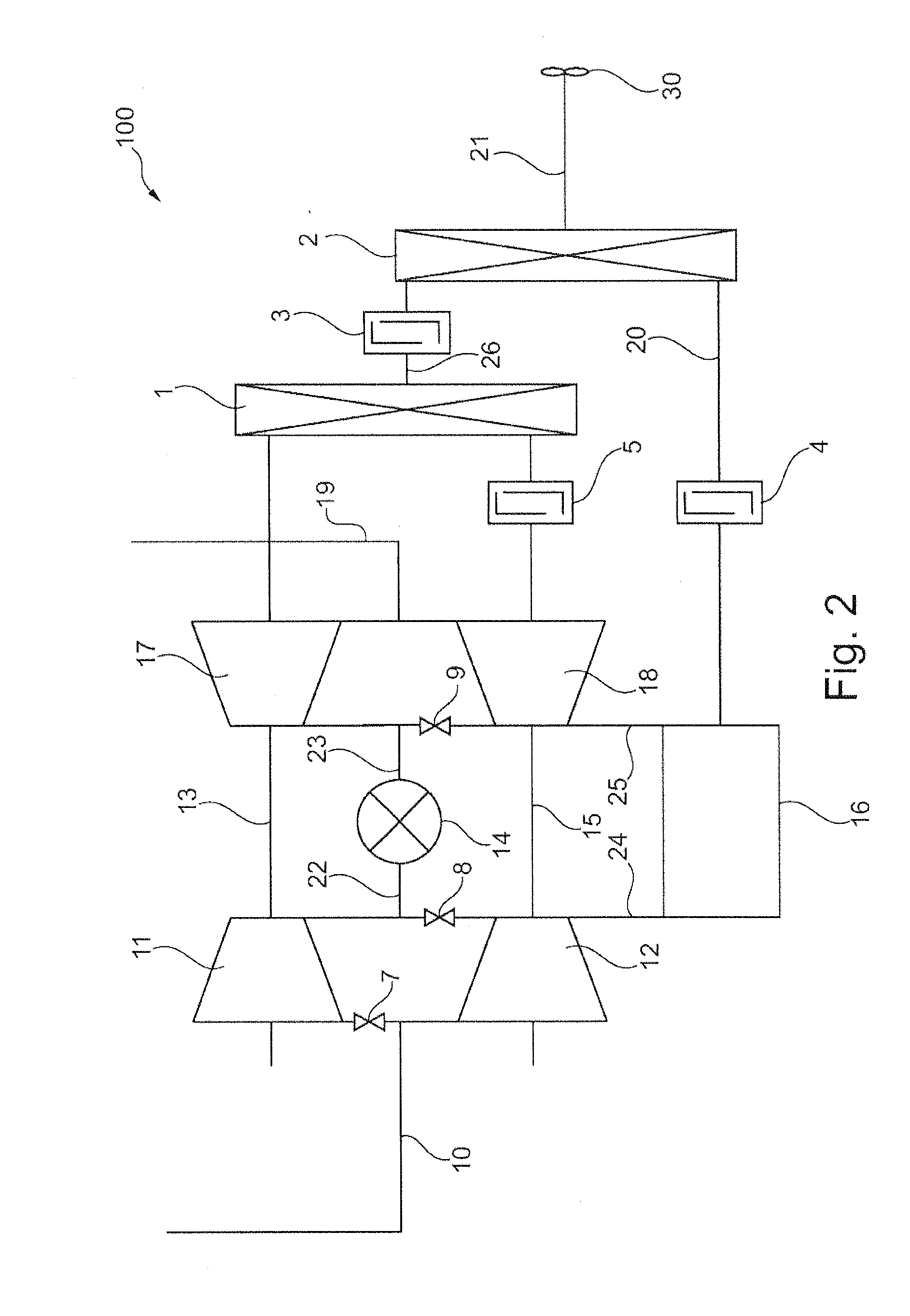
[0047]FIG. 2 shows a circuit diagram for a compound engine 100 for a parallel arrangement of compressors 11, 12 and turbines 17, 18 and a diesel engine 16 as well as mechanical transmissions 1, 2. In this design the compressor 11 and the turbine 17 are arranged on a shaft 13, the compressor 12 and the turbine 18 are arranged on a further shaft 15, and the diesel engine is also arranged on its own shaft 20.

[0048]In the concept shown, air is channeled, by way of the fresh air supply 10,...


PUM


Abstract

A compound engine for a means of transportation, includes a diesel engine and a gas turbine with at least one compressor and with at least one turbine. The diesel engine and the gas turbine are interconnected in such a manner that during continuous duty operation the compound engine is configured to be operated only by way of the diesel engine, and the diesel engine is optionally operated on its own or together with a compressor and a turbine of the gas turbine as a turbocharger for the diesel engine. The compound engine is configured to be operated by way of the diesel engine or the gas turbine.

Description

CROSS-REFERENCE TO RELATED APPLICATIONS[0001]The present application is a continuation of International Application No. PCT / EP2011 / 066948, filed Sep. 29, 2011, which claims priority from German Patent Application No. 10 2010 046 850.9, filed Sep. 29, 2010, the disclosures of which are hereby incorporated herein by reference.FIELD OF THE INVENTION[0002]The invention relates to an engine in a means of transport. In particular, the invention relates to a compound engine comprising a diesel engine and a gas turbine, to the use of such a compound engine in a means of transport, to a means of transport with such a compound engine, and to methods for driving a means of transport with such a compound engine.BACKGROUND OF THE INVENTION[0003]Both diesel drives and gas turbine drives are used in the present-day state of the art.[0004]Diesel technology is in widespread use as a drive in motor vehicles, in aircraft and in ships or boats. Said diesel technology is characterized by high efficiency...

Claims


Application Information

Patent Timeline
IPC IPC(8): F02B63/00
CPCB63H21/20B64D27/04B64D27/10B64D2027/026F01D15/04Y02T50/44F02B37/166Y02T10/144F05D2220/40F02B63/00F02B37/105Y02T10/12Y02T50/40
Inventor STUCKI, STEFAN
Owner AIRBUS OPERATIONS GMBH
Why Eureka
Try Eureka