Internal combustion engine exhaust brake control method and device

a technology for internal combustion engines and brakes, which is applied in the direction of electrical control, machines/engines, mechanical equipment, etc., can solve the problems of increased internal pressure of exhaust pipes, increased engine friction, increased engine friction, etc., and achieves the effect of increasing braking for

Inactive Publication Date: 2013-08-22
ISUZU MOTORS LTD
View PDF5 Cites 14 Cited by
  • Summary
  • Abstract
  • Description
  • Claims
  • Application Information

AI Technical Summary

Benefits of technology

[0018]According to the present invention, it is possible to increase the braking force by increasing the exhaust pipe internal pressure...

Problems solved by technology

Then, the intake air amount increases, the air is discharged from the engine, the exhaust pipe internal pressure increases...

Method used


Image

  • Internal combustion engine exhaust brake control method and device
  • Internal combustion engine exhaust brake control method and device
  • Internal combustion engine exhaust brake control method and device

Examples


Embodiment Construction

[0024]Hereinafter, a preferred embodiment of the present invention will be described by referring to the accompanying drawings.

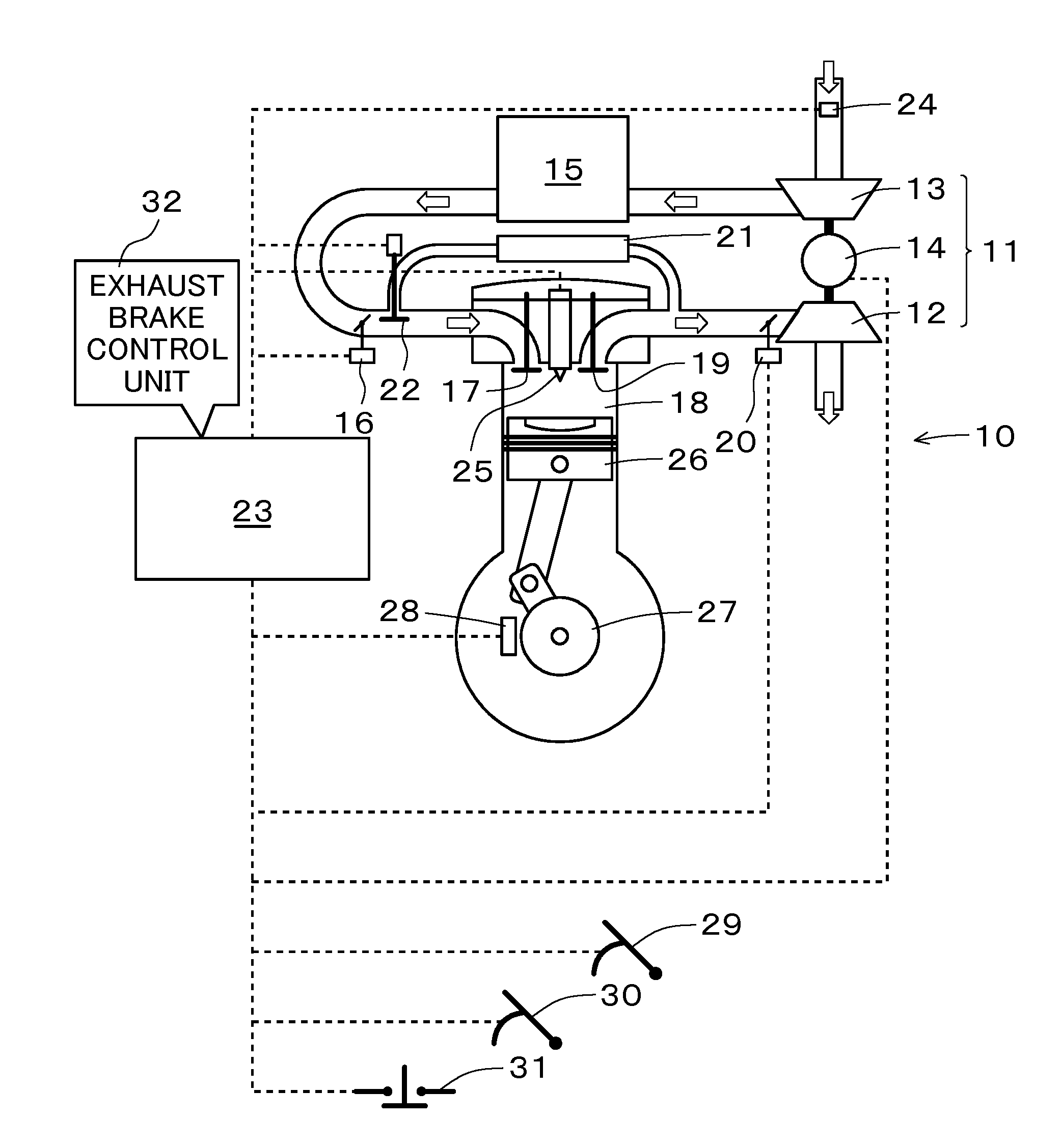
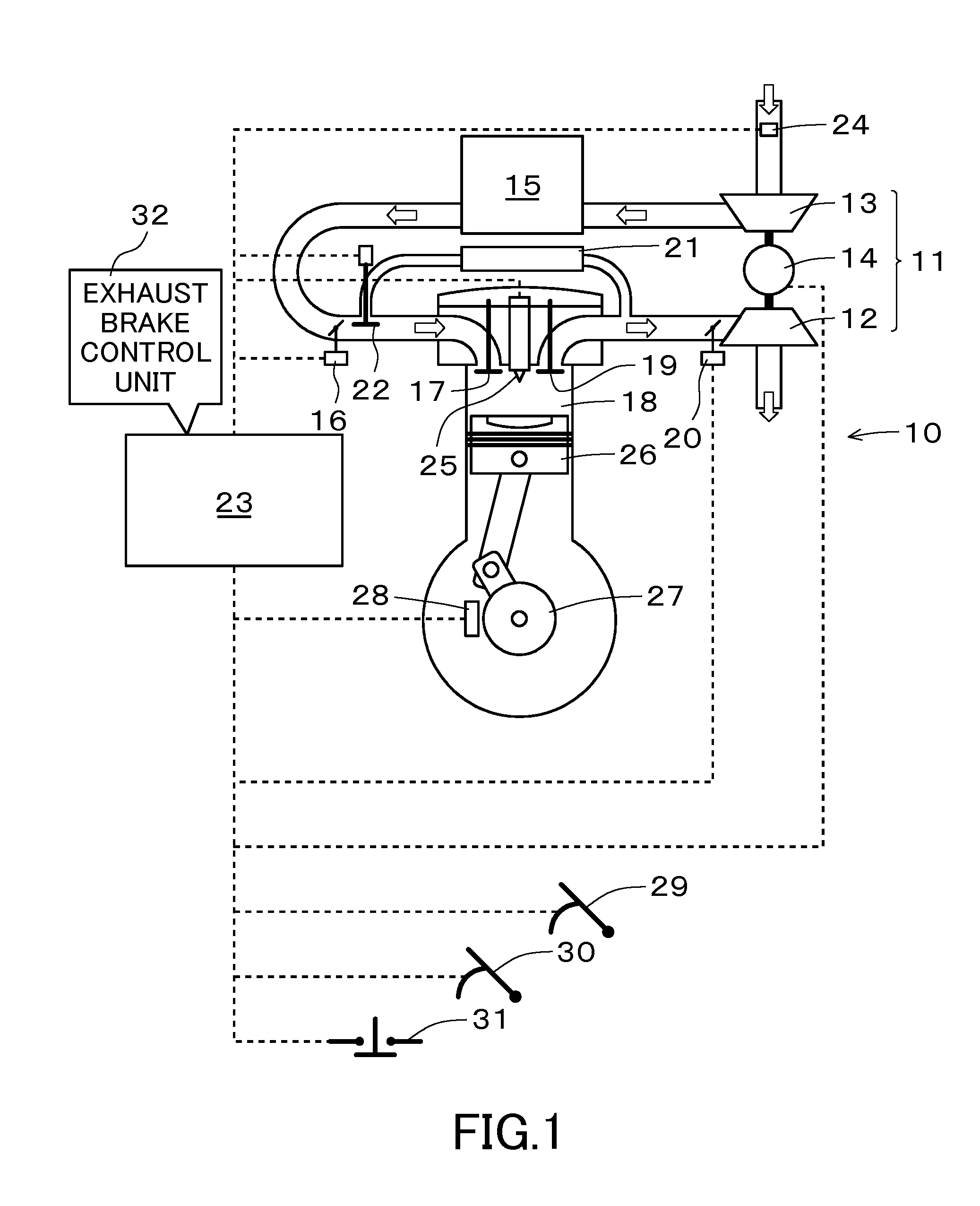
[0025]FIG. 1 is a schematic diagram illustrating an example of an engine which becomes a subject of the present invention.

[0026]As illustrated in FIG. 1, in an engine 10 which becomes a subject of the present invention, an electric turbocharger 11 is connected to an intake system, a turbine (exhaust turbine) 12 of the electric turbocharger 11 is driven by the exhaust energy, and then a supercharging operation is performed by a compressor (intake compressor) 13.

[0027]The electric turbocharger 11 may rotate the turbine 12 and the compressor 13 which are present at the same shaft by a motor 14, so that an arbitrary rotation may be obtained regardless of the flow rate of the exhaust gas. As the electric turbocharger 11, for example, a variable capacity supercharger with a motor or a supercharger capable of controlling an arbitrary compressor rotation speed may b...


PUM


Abstract

An internal combustion engine exhaust brake control method for increasing a braking force by increasing an exhaust pipe internal pressure when performing exhaust brake control by a vehicle in which an electric turbocharger is connected to an intake system of an engine. The method drives an electric turbocharger to increase a compressor rotation speed to a predetermined rotation speed and to increase an intake air amount when performing exhaust brake control by the vehicle in which the electric turbocharger is connected to the intake system of the engine.

Description

TECHNICAL FIELD[0001]The present invention relates to an internal combustion engine exhaust brake control method and an internal combustion engine exhaust brake control device for obtaining a braking force by increasing an exhaust pipe internal pressure to increase an intake and exhaust resistance and to increase a rotation resistance of an engine.BACKGROUND ART[0002]An exhaust brake which is usually mounted as a kind of an assist brake on a truck, a bus or the like having a vehicle weight of 3.5 t or more includes a valve (opening and closing valve) which is attached to an exhaust pipe at the downstream side of an engine, and a braking force is exerted by closing the opening and closing valve so as to close the exhaust pipe.[0003]The opening and closing valve is opened or closed by a force generated by a compression or a negative pressure of air or electricity, and in general, the opening and closing valve is used as an exhaust brake while being closed only in a state where a clutc...

Claims


Application Information

Patent Timeline
IPC IPC(8): F02D9/06
CPCF02B27/04F02B37/10F02B37/24F02B39/10F02D9/06Y02T10/144F02D41/0007F02D2250/34F02M25/0707Y02T10/146F02D23/00F02D41/0005F02D41/022F02D41/123F02M26/05Y02T10/12Y02T10/40
Inventor WATANABE, YOSHINOBUNITTA, JUNICHIRO
Owner ISUZU MOTORS LTD
Why Eureka
Try Eureka