Eureka AIR delivers breakthrough ideas for toughest innovation challenges, trusted by R&D personnel around the world.

Discharge type battery management system and method thereof

Inactive Publication Date: 2013-08-22
LEE JIA YUAN
View PDF6 Cites 9 Cited by
  • Summary
  • Abstract
  • Description
  • Claims
  • Application Information

AI Technical Summary

Benefits of technology

The present invention provides a discharge type battery management system and method that can maintain the battery units at the same potential, enhance the conversion efficiency of the battery pack and delay the aging of the battery units. The system includes a monitoring unit to monitor the electric potential, current, and temperature of the battery units and a control unit to manage the battery pack. If the monitoring unit detects that one of the battery units has a relatively higher potential, it will output a discharge signal to the control unit. The control unit will then activate a switch to discharge the excess electric energy from the corresponding battery unit to an energy storage unit, which then sends the energy back to the system to balance the electric potential of each battery unit. To prevent damage to the battery pack from overcharging, the system also includes a power disconnection switch and a temperature sensor to shut off the power supply and prevent damage to the battery pack. In addition, each of the first coils is coupled to a synchronous rectifier element through a third switch to improve the efficiency of the battery pack and ensure simultaneous charging of each battery unit.

Problems solved by technology

However, there generally exists a slight difference of the properties among the battery units, such as a different internal resistance allows accommodating and outputting different electric power during the discharge.
After the discharge is repeated for several times, a voltage difference exists between the battery units to cause an unbalanced electric potential between the battery units and lower the performance and efficiency of the battery pack.
If the electric potential of the battery unit is too high, the battery will be aged sooner or even burned.
On the other hand, if the electric potential is too low, the battery will be aged or damaged easily.
However, this passive method of equalizing the electric potential of the battery produces heat by the energy consumption of the resistors and results in an increased temperature that will shorten the service life of the battery pack, lower the energy conversion efficiency, and have difficulty of expansion.

Method used


Image

  • Discharge type battery management system and method thereof
  • Discharge type battery management system and method thereof
  • Discharge type battery management system and method thereof

Examples


Embodiment Construction

[0013]The technical content of the present invention will become apparent with the detailed description of preferred embodiments and the illustration of related drawings as follows.

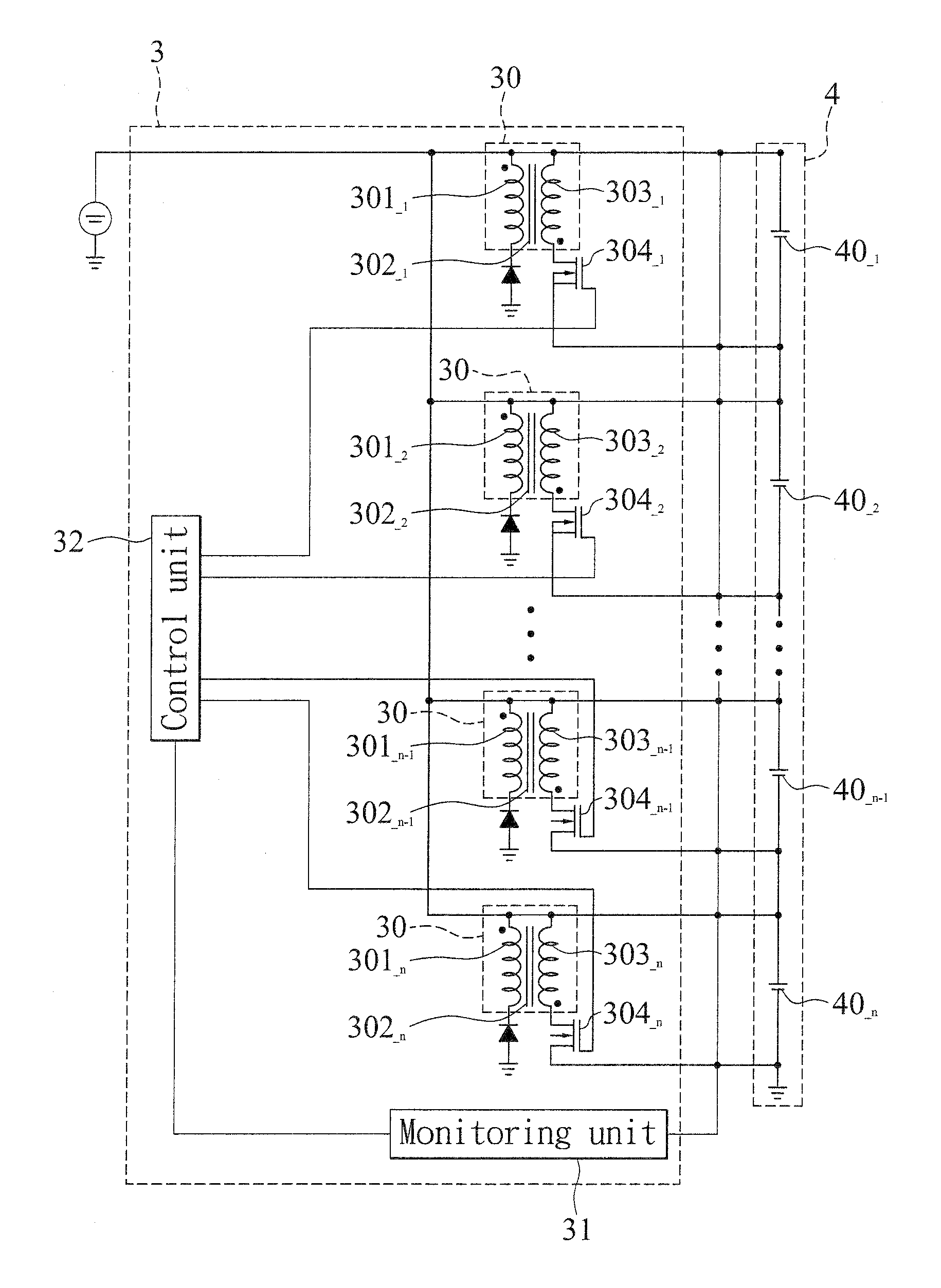
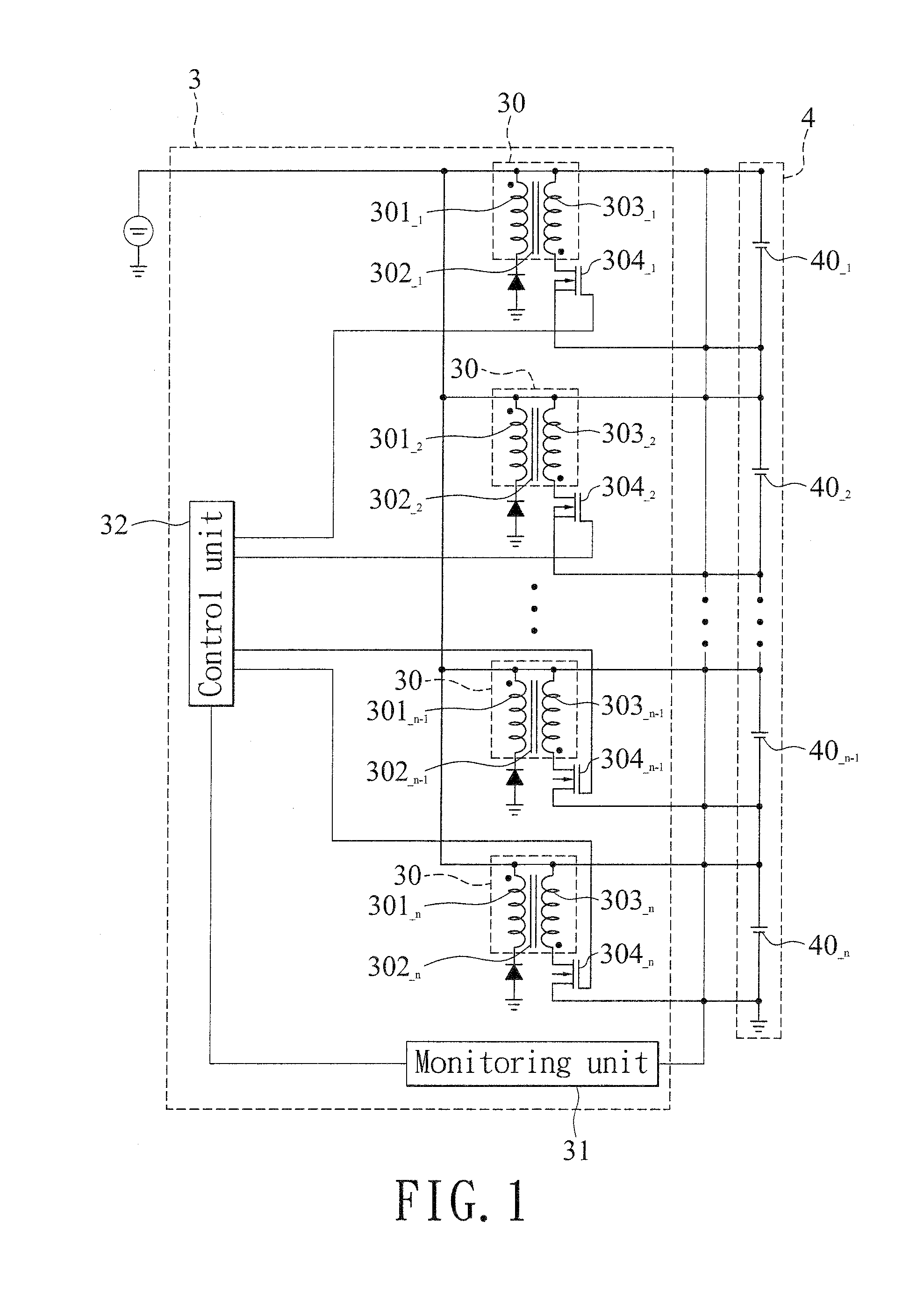
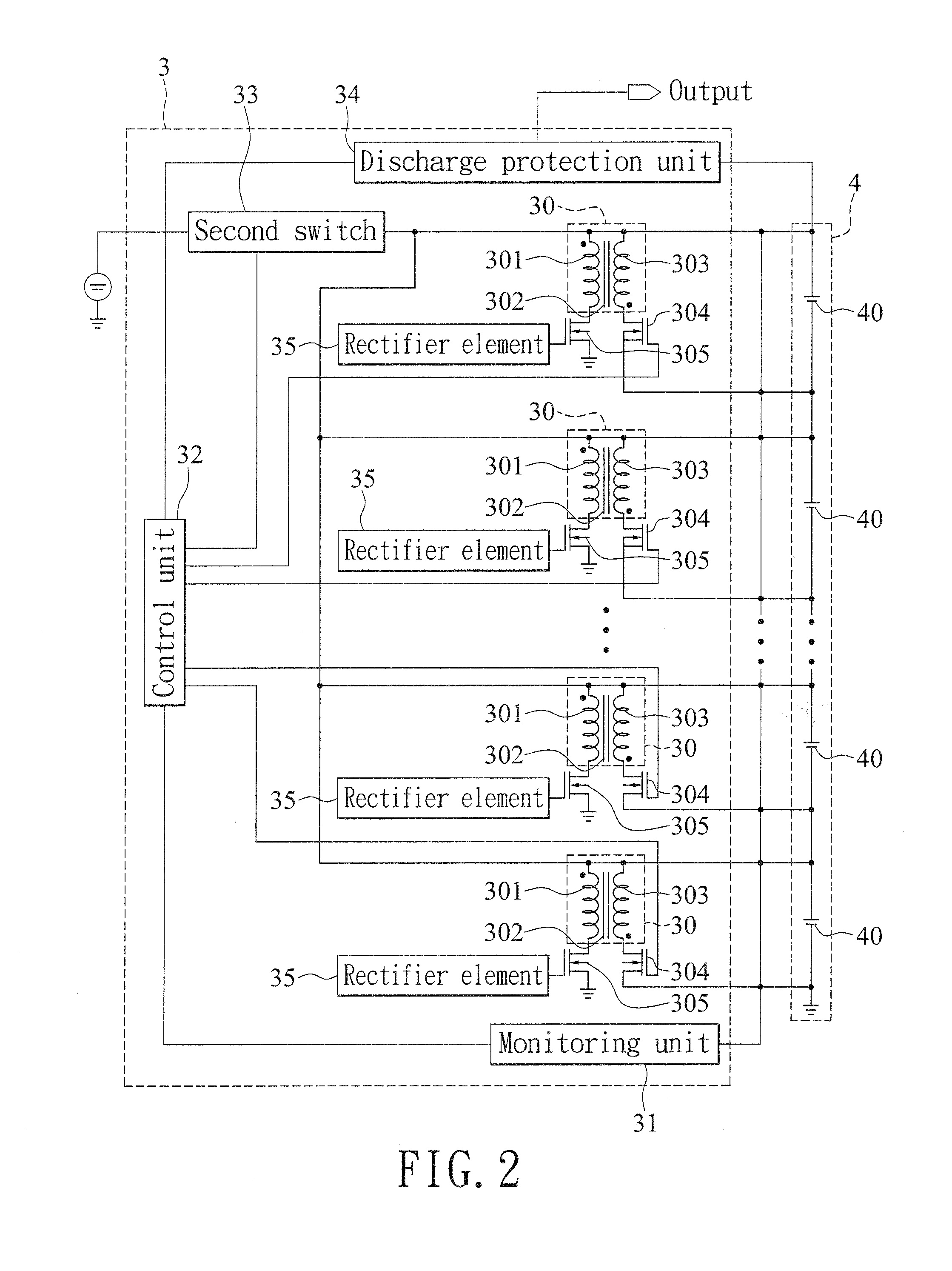
[0014]With reference to FIGS. 1 and 2 for schematic circuit diagrams of the first and second preferred embodiments of the present invention respectively, the discharge type battery management system 3 is used for charging and monitoring a plurality of battery units 40 of a battery pack 4. The discharge type battery management system 3 comprises a plurality of energy storage units 30, a monitoring unit 31, a control unit 32, a second switch 33 and a discharge protection unit 34. Each energy storage unit 30 comprises a first coil 301, a magnetic core 302 and a second coil 303, wherein each first coil 301 is coupled to the second coil 303 through the magnetic core 302, and each second coil 303 is coupled to the battery unit 40 through a first switch 304. The monitoring unit 31 is electrically coupled to the ...


PUM


Abstract

In a discharge type battery management system and a method thereof, a monitoring unit is used to monitor a plurality of battery units, and if there is a change of electric potential, current and temperature of the battery units, a control unit controls a plurality of separate energy storage units, so that when the battery pack is charged, at least one of the battery units with a relatively high potential is discharged to equalize the overall electric potential of the battery pack, so as to enhance the energy conversion efficiency.

Description

BACKGROUND OF THE INVENTION[0001]1. Field of the Invention[0002]The present invention relates to the technical field of electric energy conversion adjustment circuits, in particular to a discharge type battery management system and a method thereof having a control unit to control a discharge switch, and an independent energy storage unit to discharge at least one high-potential battery unit, so as to achieve the effect of equalizing the electric potential of each battery unit.[0003]2. Description of the Related Art[0004]At present, most green transportation means such as electric cars or hybrid cars adopt lithium-iron battery as a repeated discharge battery pack for the supply of kinetic energy. Since a single lithium-iron battery generally has a voltage of approximately 3˜4 volts which much lower than the required driving voltage (100 volts) of the electric or hybrid cars, therefore the battery pack for supplying kinetic power is compulsorily formed by connecting a plurality of li...

Claims


Application Information

Patent Timeline
IPC IPC(8): H02J7/00
CPCH02J7/0016Y02T10/7055H02J7/0026H02J7/0021Y02T10/70H02J7/00302H02J7/0048
Inventor LEE, JIA-YUANBENEY, PIERRE-JEAN
Owner LEE JIA YUAN
Why Eureka
Eureka Blog
Learn More