
Predictive maintenance method for a cooled detection module, and related module

a detection module and maintenance method technology, applied in the field of prediction maintenance methods of cooled detection modules, can solve the problems of inability to optimise preventive maintenance, drawbacks of the above techniques, and the service life of the equipmen

Active Publication Date: 2013-08-22
SAFRAN ELECTRONICS & DEFENSE
View PDF2 Cites 0 Cited by
  • Summary
  • Abstract
  • Description
  • Claims
  • Application Information

AI Technical Summary

Benefits of technology

The patent text describes a technology that allows for real-time monitoring of the electric consumption of a cryostat and a detector. This helps to identify any potential problems with the equipment and prevent untimely failures. If a problem is detected, maintenance can be carried out to address it, reducing downtime. The technology can also be used to optimize preventive maintenance by taking into consideration the type of use the equipment is being used for. Overall, this technology helps to keep the equipment running smoothly and at optimal performance.

Problems solved by technology

Such a DM comprises movable elements intrinsically limiting the service life of the equipment.
Indeed, the cooling phase is a critical period for the CM, since the constituents of the CM are subject to intensive use.
However, the above techniques involve drawbacks.
DM preventive maintenance ensures that the user of the DM can avoid failures associated with ageing of the DM, but does not account for the actual condition of the DM.
Likewise, it does not enable optimisation of preventive maintenance, since it does not account for the operating mode of the CM.
Indeed, the operating time of a DM, generally expressed in a number of hours of operation, remains statistical and is not suitable for accounting for disparities in production and / or use.
For this reason, it is not possible for the user to maximise the benefit from the durability of the DM within the scope of standardised use.
Moreover, the techniques according to FR 2 930 677 and FR 2 930 678 are not suitable for detecting a fault wherein the CM is degraded such as following continuous operation for a long period of time.
Likewise, they are not suitable for distinguishing between the need for a preventive maintenance procedure (such as pumping up the CM—i.e. injecting gas into the CM, to compensate for the losses thereof due to leakages, or such as gettering the cryostat—i.e. regenerating the gas trap (also referred to as “getter”), for example by circulating strong currents in the gas trap, to ensure the quality of the vacuum of the cryostat, etc.) and the need for equipment replacement, for example in the event of severe mechanical failure.

Method used


Image

  • Predictive maintenance method for a cooled detection module, and related module
  • Predictive maintenance method for a cooled detection module, and related module
  • Predictive maintenance method for a cooled detection module, and related module

Examples


Embodiment Construction

[0022]The invention proposes to remedy at least one of these drawbacks. For this purpose, according to a first aspect, the invention relates to a predictive maintenance method for a cooled detection module, comprising:[0023]a detector comprising pixels that are sensitive to light signals;[0024]a cryostat, containing the detector; and[0025]a cooling machine,

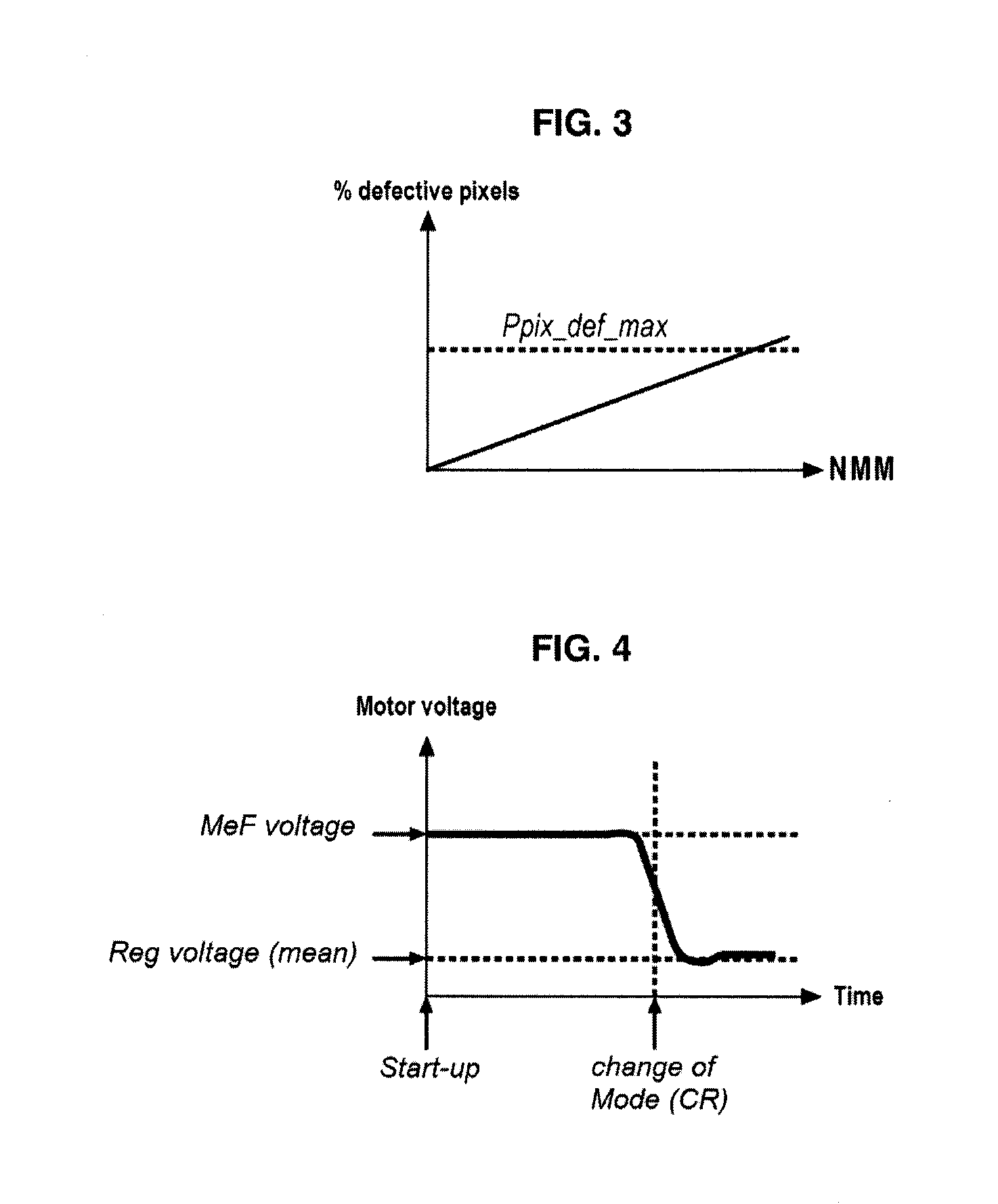
the method being characterised in that it comprises a step whereby a processing board of the module, which is electrically connected to the detector, to the cryostat and to the cooling machine, measures, stores and processes at least[0026]one motor current, i.e. a machine supply current;[0027]one motor voltage, i.e. a machine supply voltage; and[0028]a number of defective pixels of the detector.

[0029]According to the first aspect thereof, the invention advantageously further comprises the following features, alone or in any technically possible combination thereof:[0030]the board is further suitable for[0031]measuring, storing and...


PUM


Abstract

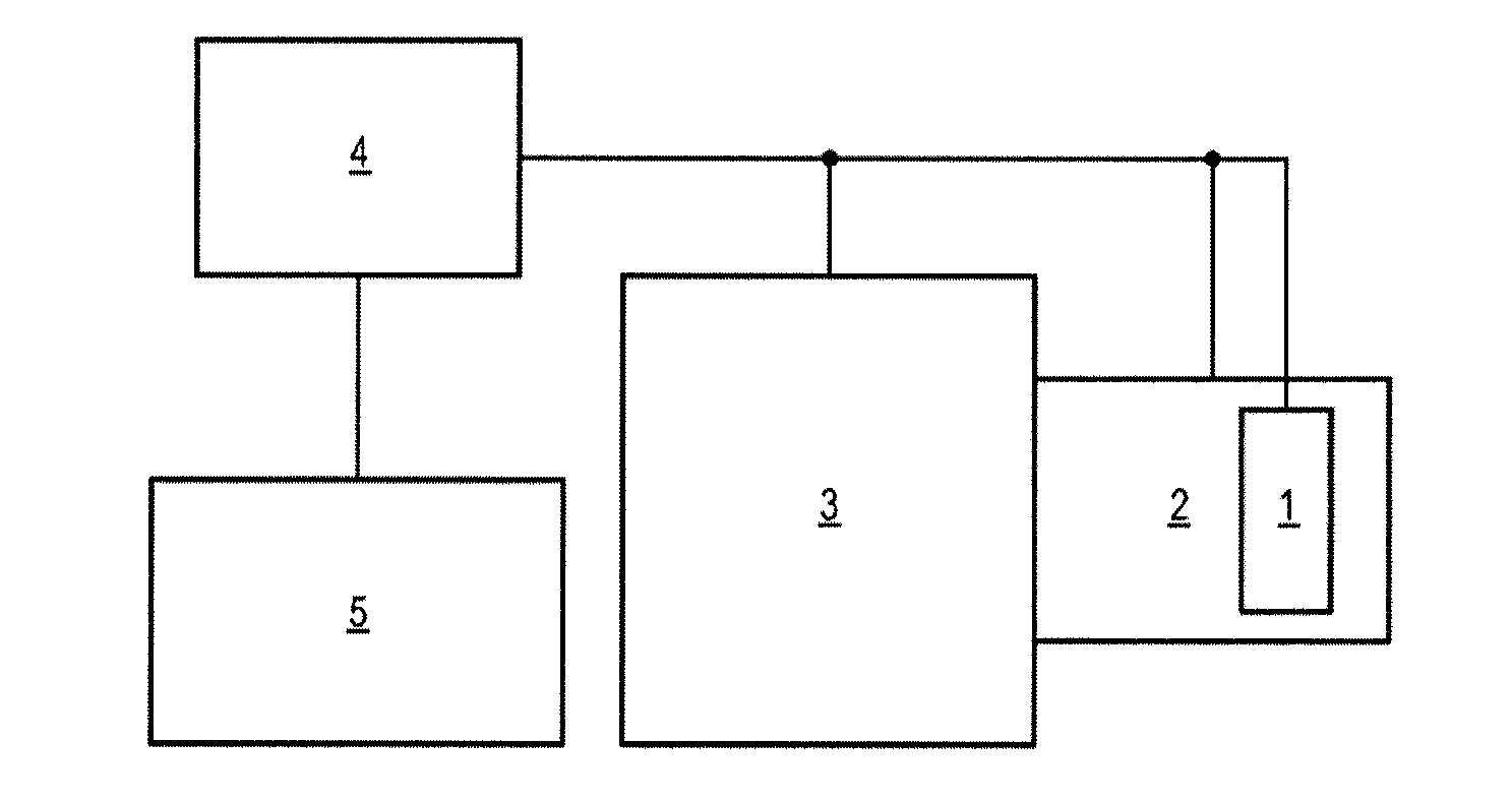
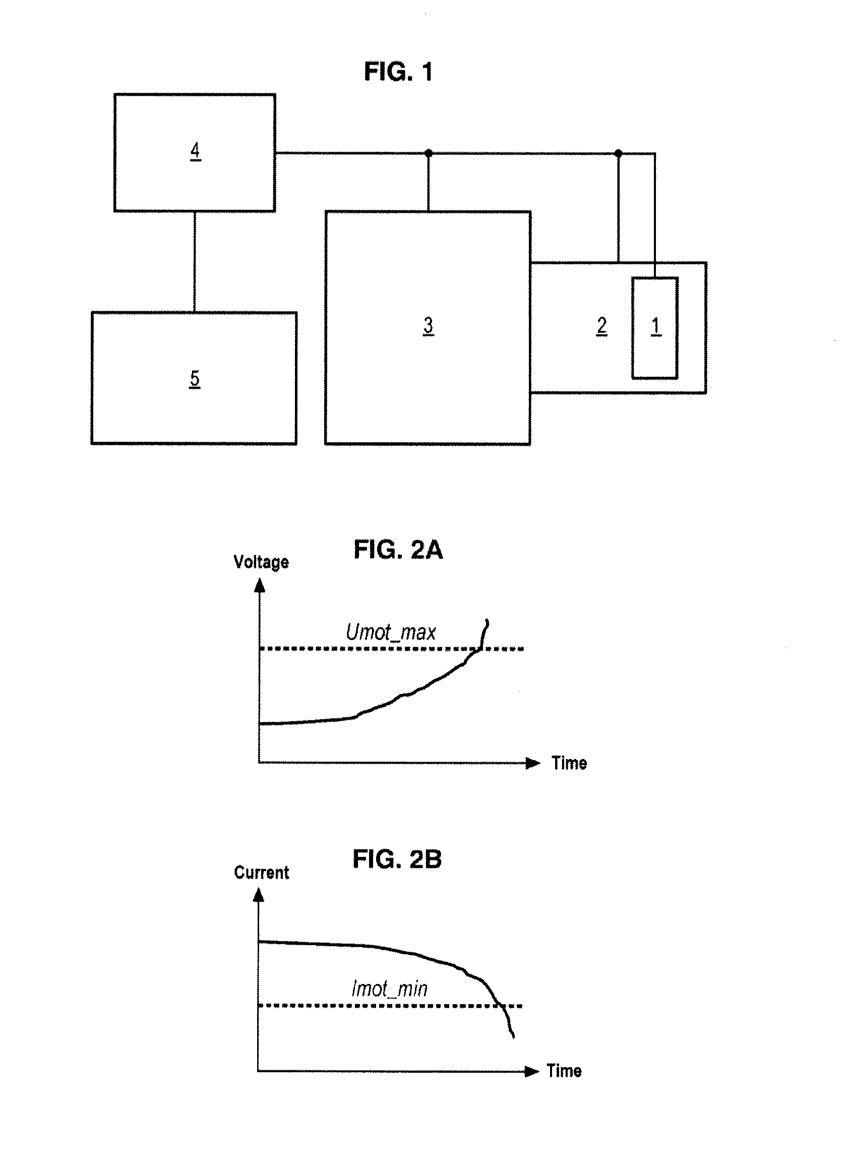
The invention relates to a predictive maintenance method for a cooled detection module, comprising: a detector (1) comprising a matrix consisting of pixels that are sensitive to light signals; a cryostat (2) containing the detector (1); and a cooling machine (3), said method being characterized in that it comprises a step according to which a processing board (4) of the module, which is electrically connected to the detector (1), to the cryostat (2), and to the cooling machine (3) measures, stores, and processes at least: one motor current, i.e. a supply current of the machine (3); one motor voltage, i.e. a supply voltage of the machine (3); and a number of defective pixels of the detector (1). The invention further relates to a module for implementing the invention.

Description

GENERAL FIELD OF THE INVENTION[0001]The present invention relates to a predictive maintenance method for a cooled detection module, comprising a detector comprising pixels that are sensitive to light signals, a cryostat, containing the detector, and a cooling machine.[0002]It also relates to a module for implementing the method.STATE OF THE RELATED ART[0003]Known optronic systems operating in the infrared (IR) range frequently comprise so-called cooled detection modules (DM), i.e. wherein the detector is cooled to a very low temperature (−170° C.). The performances obtained are superior to those of non-cooled DMs.[0004]Conventionally, a cooled IR DM comprises:[0005]an IR detector, sensitive to IR light signals;[0006]a cryostat, containing the IR detector and used for mechanically conditioning the detector and providing thermal insulation, so as to limit the energy consumption of the cooled DM; and[0007]an electro-mechanical cooling machine (CM), used to reduce the cryostat temperatu...

Claims


Application Information

Patent Timeline
Patent Type & Authority Applications(United States)
IPC IPC(8): G06F11/30
CPCF25B49/005F25B2700/151F25D19/00G06F11/30G01J5/045G01J5/061G01J5/026
Inventor PICARD, AUBRYTILLARD, THOMAS
Owner SAFRAN ELECTRONICS & DEFENSE
Learn More