Furrow cutter

a cutter and furrow technology, applied in the field of furrow cutters, can solve problems such as the breakage of the blade, and achieve the effects of increasing the width of the blade, good work results, and easy production

Active Publication Date: 2013-09-05
ANDREAS STIHL AG & CO KG
View PDF7 Cites 5 Cited by
  • Summary
  • Abstract
  • Description
  • Claims
  • Application Information

AI Technical Summary

Benefits of technology

The invention is a furrow cutter with a simple structure that provides good work results. The blade has a fastening region that allows for controlled wear and a good geometry of the plowed furrow. The blade is easily produced with a short frame structure and is designed to be pulled over the lawn area. The arm of the blade is bent at two bending lines, which allows for an inclined position of the blade when in use. The blade has a wear section at the front in the direction of rotation and is made from a single sheet metal part. The technical effects of the invention are improved work efficiency, better geometry of the plowed furrow, and increased wear resistance.

Problems solved by technology

In blades which are formed as a frame structure, wear in a region which connects two sections of the blade together can result in the blade breaking apart.

Method used


Image

  • Furrow cutter
  • Furrow cutter
  • Furrow cutter

Examples


Embodiment Construction

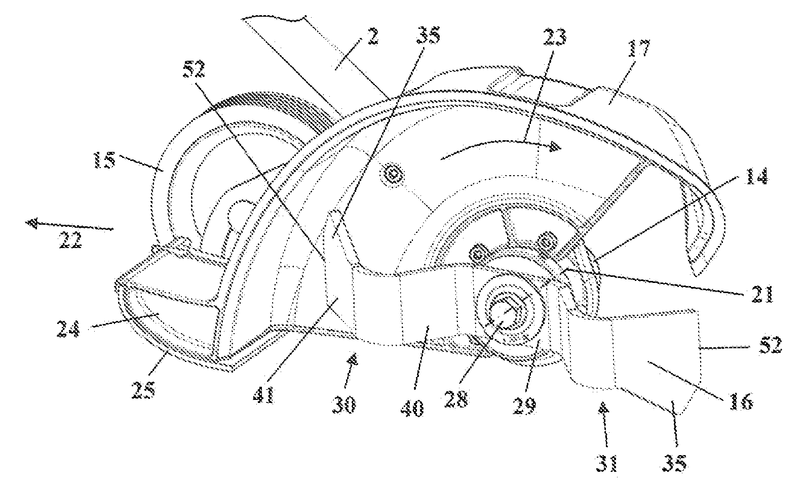
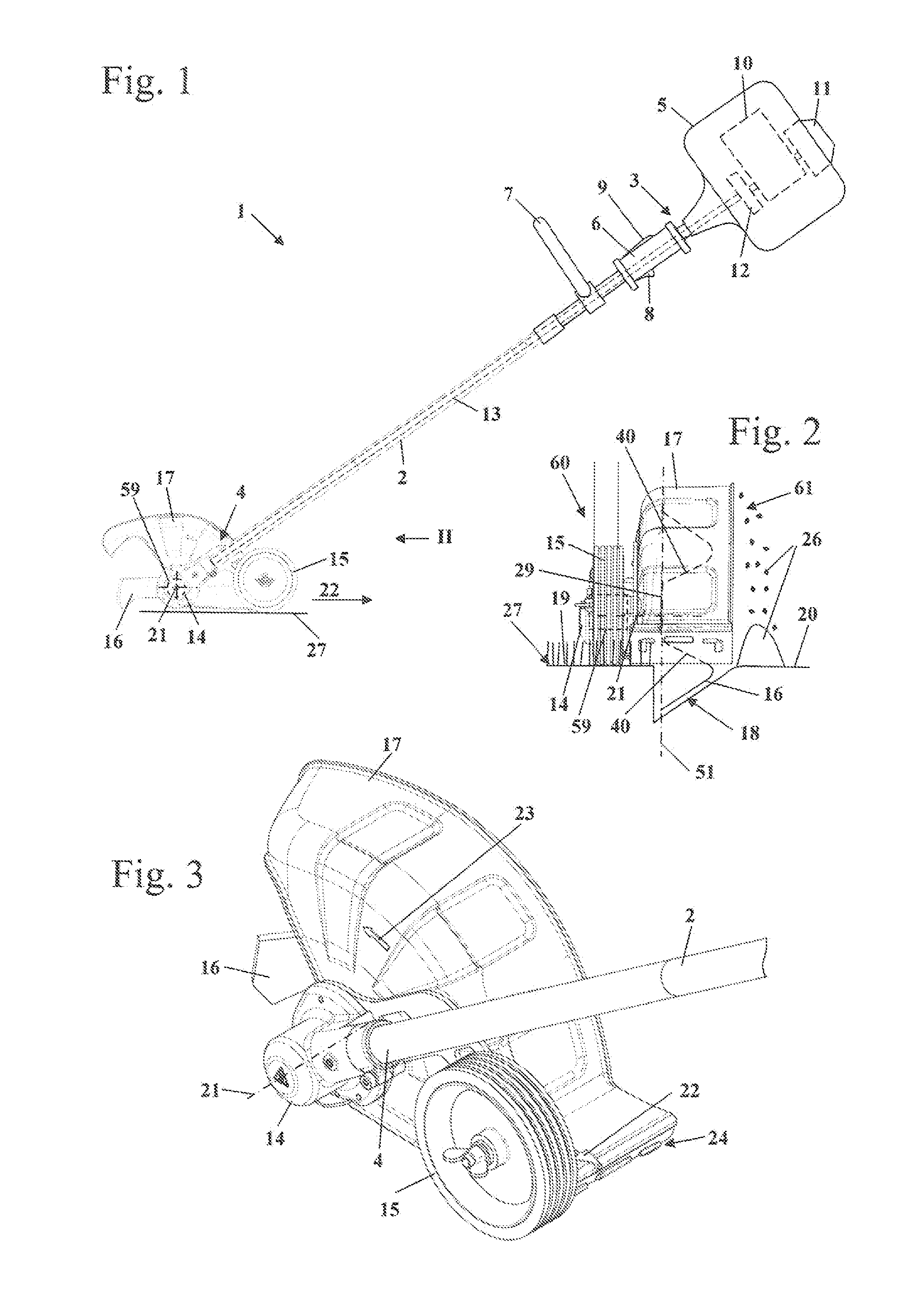
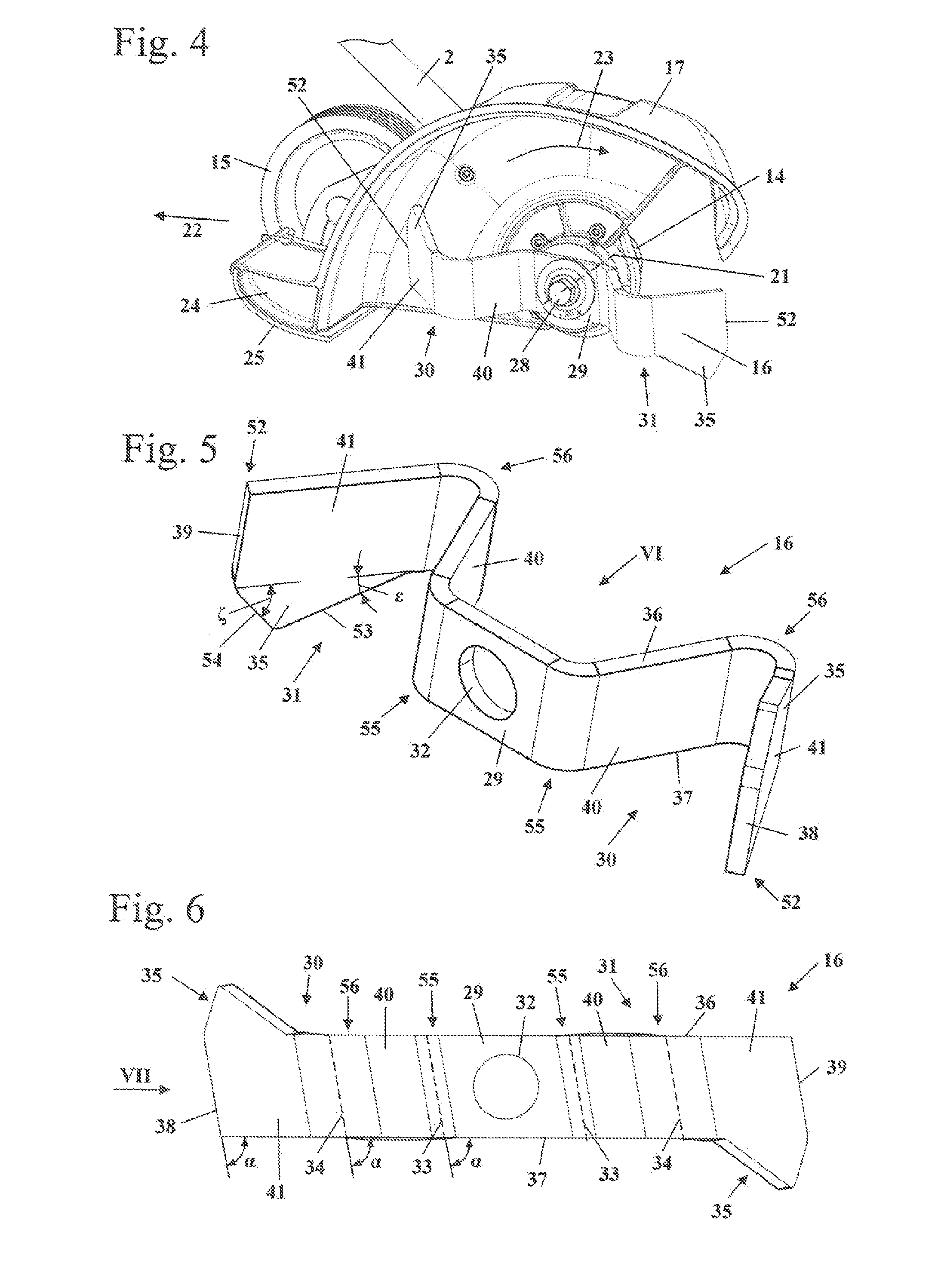
[0023]FIG. 1 shows a furrow cutter 1. Such furrow cutters, also called bed redefiners, are used in order to plow a furrow between a lawn area and adjoining bed areas or the like and thus to create a clear boundary between these areas. However, the blade of the present invention can also be used in other work apparatuses, for example in edge cutters (edgers) or the like. Use in brush cutters, in particular as chopping blades, can also be advantageous.

[0024]The furrow cutter 1 has a guide tube 2, at the first, during normal operation upper, end 3 of which a motor housing 5 is fixed. At the other, second end 4, which faces the ground 27 during operation, there is arranged a cutting head. A handle 6, which engages around the guide tube 2, is fixed to the guide tube 2 adjacent to the motor housing 5, a throttle lever 8 and a throttle lever lock 9 being mounted on said handle 6. Further operating elements can also be arranged on the handle 6. On that side of the handle 6 that faces the cu...


PUM


Abstract

A blade for a furrow cutter has a planar fastening region which is located in a fastening plane. The blade is driven in rotation via a transmission arranged in a transmission housing. The fastening plans separates a first region of the furrow cutter from a second region of the furrow cutter. The transmission is arranged in the first region. The blade has at least one arm projecting from the fastening region and having a free end. The arm has a first segment which extends out of the fastening plane into the second region. A simple structure, a good cutting result and a high service life are achieved when the arm has a second segment in which the arm extends back in the direction of the fastening plane.

Description

CROSS REFERENCE TO RELATED APPLICATION[0001]This application claims priority of European patent application no. 12001448.5, filed Mar. 2, 2012, the entire content of which is incorporated herein by reference.BACKGROUND OF THE INVENTION[0002]U.S. Pat. No. 4,072,195 discloses a blade for an edge cutter. The blade has a central fastening region from which two arras extend outward. The outer sections of the arms are formed in a shovel-shaped manner and extend away from the fastening region of the blade.[0003]DE 297 09 152 U1 discloses a blade for a lawn edging machine which has outwardly projecting arms that are bent out of the fastening plane. When this blade is used with a furrow cutter, that edge of the furrow that faces the furrow cutter extends in an inclined manner in the ground.[0004]U.S. Pat. No. 6,302,219 B1 shows a blade for a furrow cutter. The blade is configured as a frame structure and has a comparatively complex structure.SUMMARY OF THE INVENTION[0005]It is an object of t...

Claims


Application Information

Patent Timeline
Patent Type & Authority Applications(United States)
IPC IPC(8): A01G3/06
CPCA01G3/062
Inventor STARK, THOMASHAEBERLEIN, JUERGENGUENTHER, DAVID
Owner ANDREAS STIHL AG & CO KG
Why Eureka
Try Eureka