

Method and apparatus for controlling a grid-connected converter
a technology of grid connection and control method, which is applied in the direction of photovoltaic energy generation, dc-dc conversion, ac network circuit arrangement, etc., can solve the problems of compromising system stability, presenting more complex dynamics, and system with more complex filters
- Summary
- Abstract
- Description
- Claims
- Application Information
AI Technical Summary
Benefits of technology
Problems solved by technology
Method used
Image

Examples
Embodiment Construction
[0024]Exemplary embodiments of the present disclosure provide a method and an apparatus which alleviate the aforementioned disadvantages with known configurations. Exemplary embodiments of the present disclosure provide a method and an apparatus for controlling a grid-connected converter.
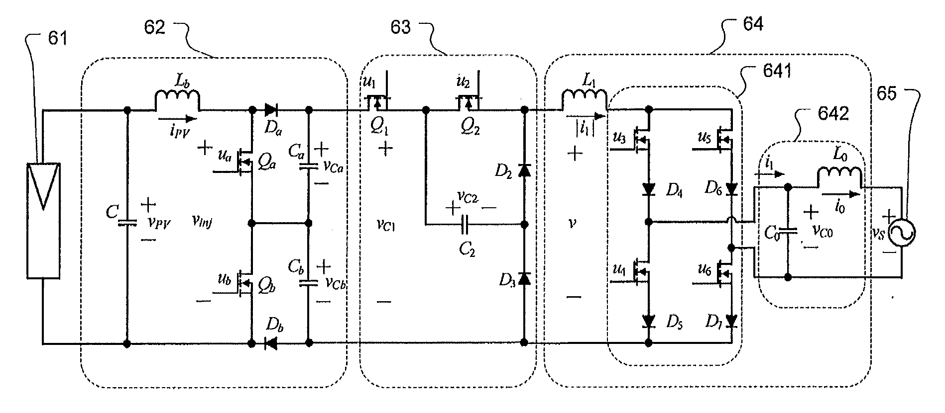
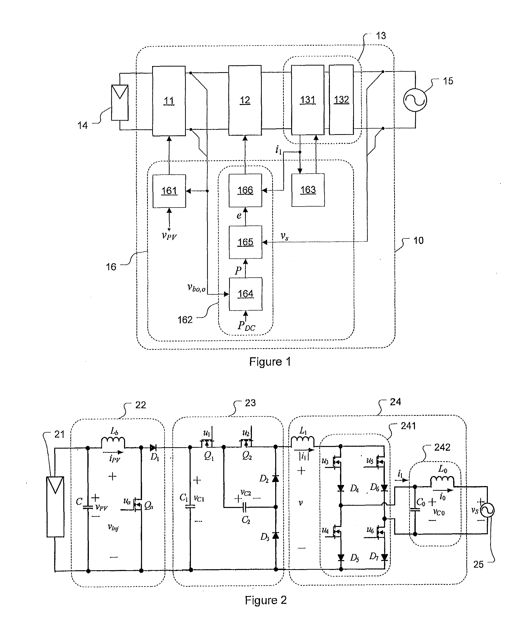
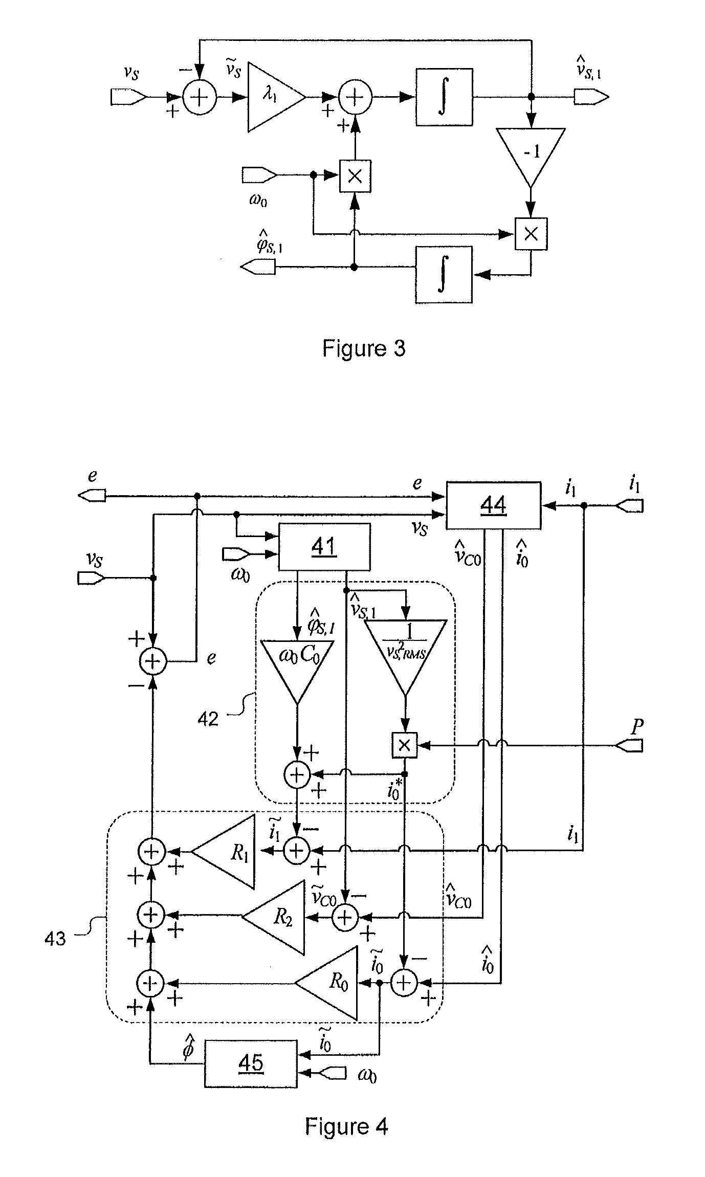
[0025]In accordance with an exemplary embodiment, a converter structure including a boost converter, a buck converter, and a current source inverter having an output CL filter can be used, in order to achieve better operational characteristics. In accordance with an exemplary embodiment, an input of the buck converter input is connected to an output of the boost converter output, and an input of the current source inverter is connected to an output of the buck converter The controller design for the converter structure can be based on a model structure. The information of the dynamical structure of the converter can be incorporated in the controller design in order to allow better dynamical performa...
PUM
 Abstract
Description
Claims
Application Information