Process for Water Treatment and Generation

a technology of water treatment and water storage, applied in the direction of vacuum distillation separation, separation process, vessel construction, etc., can solve the problems of difficult or cost prohibitive delivery of fresh water via trucking, difficulty in acquiring fresh water, and insufficient fresh water sources, so as to achieve safe human consumption, improve efficiency and throughput/footprint ratio, and reduce contaminants

Inactive Publication Date: 2013-09-12
HALLIBURTON ENERGY SERVICES INC
View PDF12 Cites 6 Cited by
  • Summary
  • Abstract
  • Description
  • Claims
  • Application Information

AI Technical Summary

Benefits of technology

[0021]In one or more embodiments, the present invention may purify contaminated water with higher efficiencies and throughput / footprint ratio as compared to conventional purification methods. In one or more embodiments, the present invention may purify the produced water out in the oilfield, which may be disposed of or recycled in subsequent subterranean operations (e.g., in subterranean treatment fluids). In one or more embodiments, the present invention provides a renewable water source that is primarily independent of environmental conditions (e.g., temperature, humidity, etc.).
[0022]Some embodiments provide a method comprising: a) providing a water generator reservoir, and a contaminated water reservoir that comprises contaminated water, wherein the water generator reservoir is fluidly connected to the contaminated water reservoir; b) volatilizing at least a portion of the contaminated water in the contaminated water reservoir to form volatilized water; c) allowing the volatilized water to be transported to the water generator reservoir; d) cooling the volatilized water in the water generator reservoir thereby generating purified water, substantially dehumidified gas, and heat; and e) allowing at least one of the substantially dehumidified gas and the heat to be transported to the contaminated water reservoir. In some embodiments, steps b), c), d), and e) are repeated as part of a cycle. Optionally, the method may further comprise: f) separating the purified water from the water generator reservoir. Optionally, the method may further comprise: removing a precipitated salt formed in the contaminated water reservoir.
[0023]Water generator reservoirs useful in the present invention may be used to extract and / or purify water from sources such as ambient air or contaminated water. As used herein, water that has been purified or “purified water” may refer to water that has been extracted from ambient air and / or to water that has been purified from a contaminated water source. The purified water will typically have lower concentration of contaminants compared to the contaminated water.
[0024]Specifically, the water generator reservoir is any type of containment or vessel that is able to store large volumes of fluids (e.g., ambient air, volatilized water). In some embodiments, the water generator reservoir may be fluidly coupled or otherwise attached to a compressor used to compress ambient air and / or volatilized water, which should allow larger masses of ambient air and / or volatilized water to be extracted and / or purified. While any compressor that is compatible with one or more embodiments may be used, an exemplary compressor may be one that is driven by a motor that may be fueled by propane or electrically driven. Suitable compressors include, but are not limited to, reciprocating compressors, rotary compressors, centrifugal compressors, axial compressors, and the like.
[0025]The water generator reservoir may also generally include and / or is otherwise fluidly coupled to a cooling means configured to dehumidify the ambient air and / or volatilized water that is contained within the water generator reservoir. Suitable cooling means include, but are not limited to, refrigerants, refrigerated coils, fans, condensing coils, heat exchangers, combinations thereof, and the like. During the dehumidification process, the water generator reservoir may produce dehumidified air and / or heat. Optionally, the water generator reservoir may include and / or is coupled to an evaporator, a pump, an air filter, and the like.
[0026]During the dehumidification process, the purified water is generally extracted from any gas contained in the water generator reservoir. In some embodiments, the purified water may undergo further treatment. Suitable examples of treatment include, but are not limited to, exposing the purified water to UV light, filtering the purified water, desalinating the purified water, subjecting the purified water to reverse osmosis, distilling the purified water, and combinations thereof. In some embodiments, the resulting purified water may be potable water and therefore safe for human consumption. In other embodiments, however, the purified water may be separated for disposal, sewage treatment, recycled in subterranean treatment fluids, and the like. The subterranean treatment fluid may be any fluid that uses water. Suitable examples of subterranean treatment fluids include, but are not limited to, drilling fluids, fracturing fluids, completion fluids, and the like.

Problems solved by technology

While fresh water is sometimes abundant, there are certain situations, particularly in oilfield applications, in which sources for fresh water are lacking.
For example, drilling may be taking place in a remote region which lacks a fresh water source and the delivery of fresh water via trucking may be difficult or cost prohibitive.
In other regions, acquiring fresh water may be difficult for legal and / or political reasons.
However, there are several issues with these conventional atmospheric water generators and their related approaches.
To date, few, if any, large scale atmospheric water generators capable of generating tens of thousands of gallons of water per day have been developed.
Moreover, conventional atmospheric water generators typically do not work well under certain atmospheric conditions, for example, low temperature (below 18.3° C.) and low humidity (below 30%).
Conventional distillation processes encounter distillation difficulties.
However, the increase in process speed may be accompanied by the undesirable precipitation of slats, minerals, and heavy metals, inducing scale build-up on the solid element and a decrease in heat transfer efficiency over time.

Method used


Image

  • Process for Water Treatment and Generation
  • Process for Water Treatment and Generation
  • Process for Water Treatment and Generation

Examples


example 1

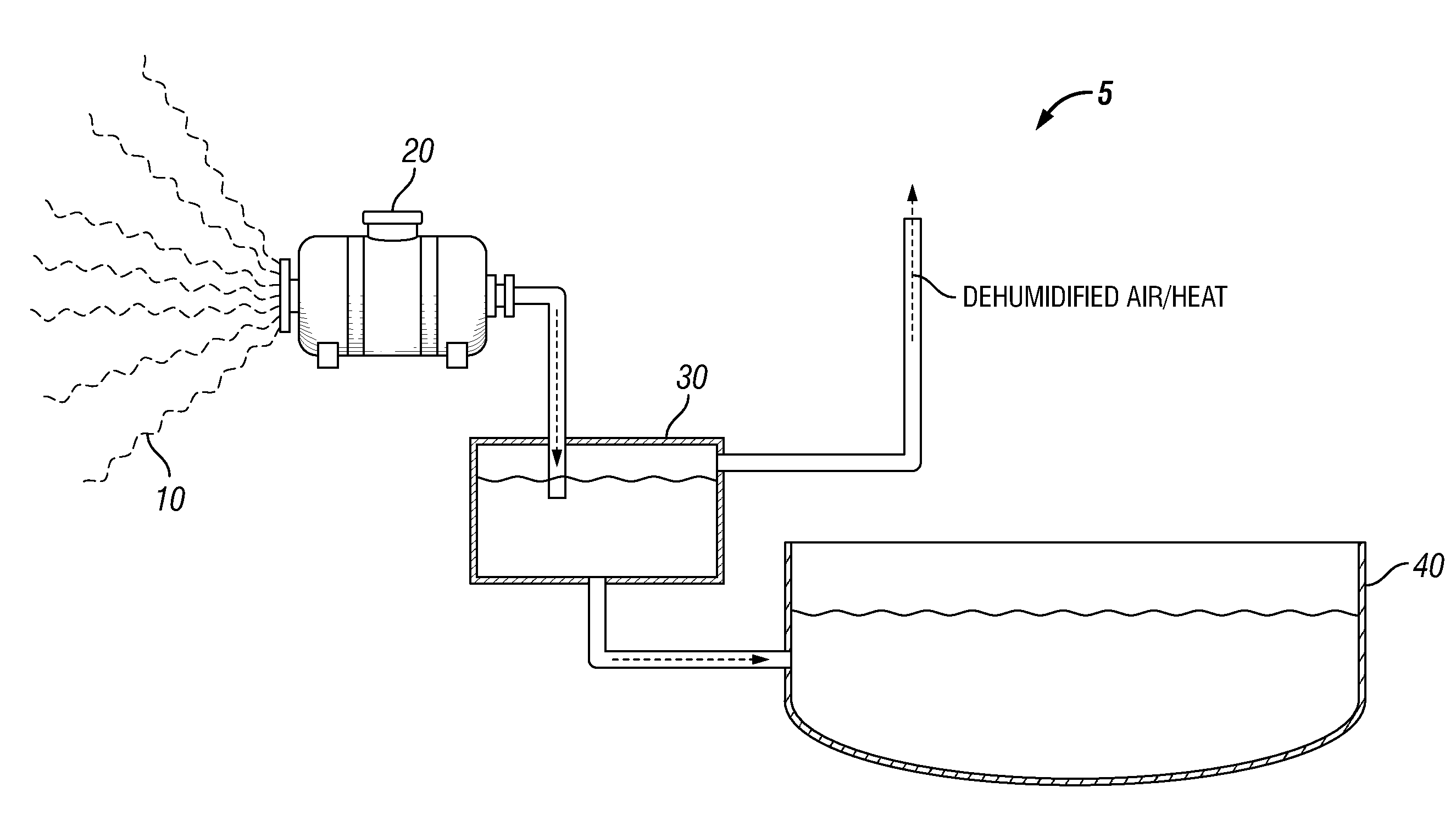
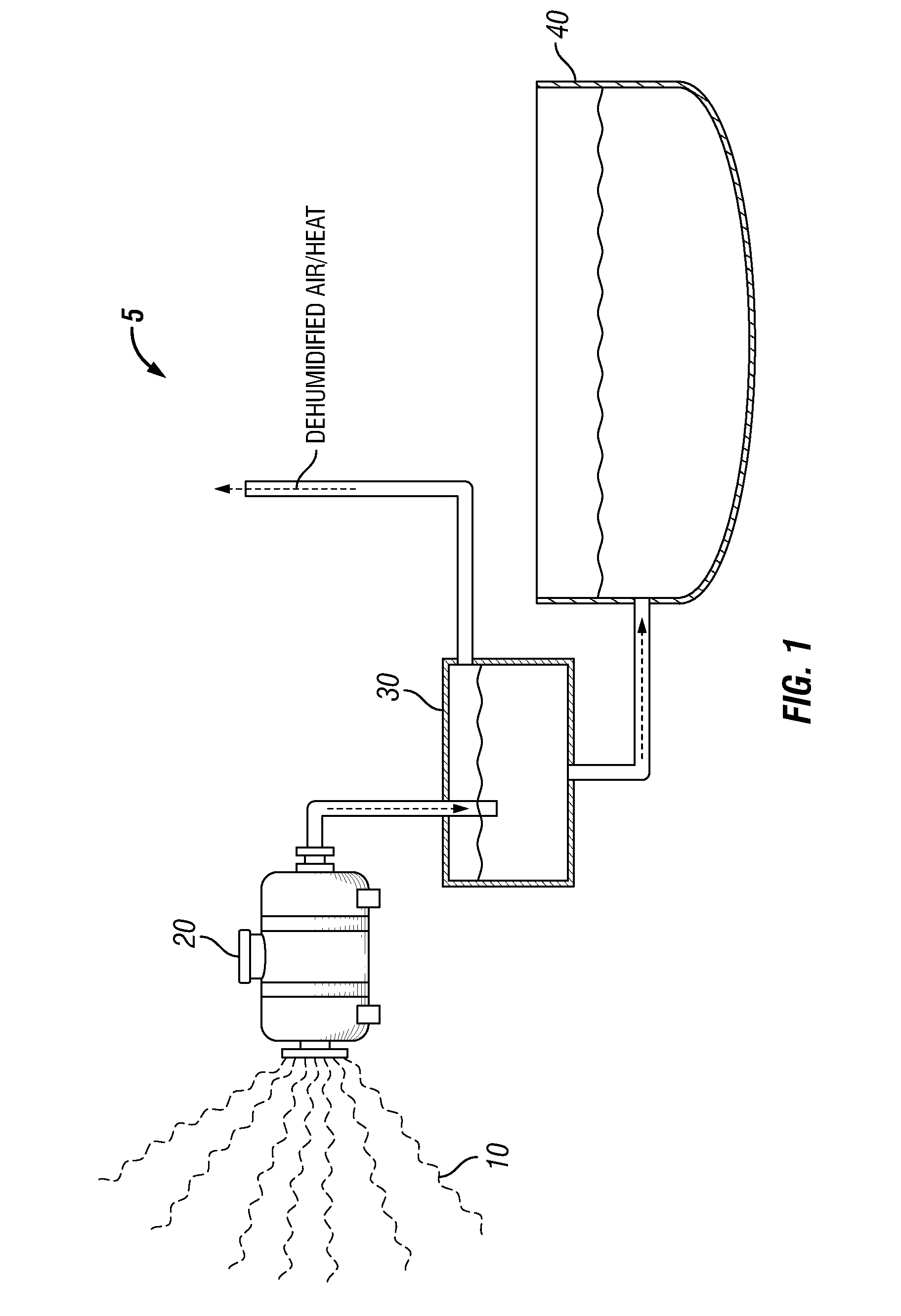
[0037]FIG. 1 shows an apparatus 5, according to one or more embodiments of the present invention. The apparatus includes a compressor 20, a water generator reservoir 30, and a purified water reservoir 40. In the embodiment shown, the water generator reservoir 30 is fluidly connected to both the compressor 20 and the purified water reservoir 40.

[0038]As shown in FIG. 1, the compressor 20 may be configured to receive and compress ambient air 10, for example, in order to generate compressed ambient air. The compressed ambient air may then be conveyed to the water generator reservoir 30. In the water generator reservoir 30, the compressed ambient air may be dehumidified by cooling in order to extract purified water and release dehumidified air and heat back into the ambient air 10. The purified water is separated and conveyed to the purified water reservoir 40 where it may be stored, for example.

example 2

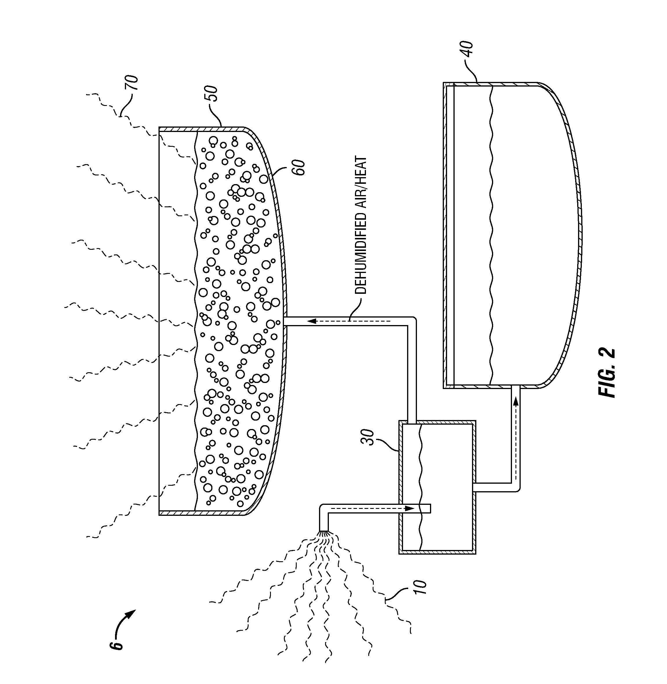
[0039]FIG. 2 shows another apparatus 6, according to one or more embodiments of the present invention. The apparatus includes a water generator reservoir 30, a purified water reservoir 40, and a contaminated water reservoir 50. In the embodiment shown, the water generator reservoir 30 is fluidly connected to the purified water reservoir 40 and the contaminated water reservoir 50.

[0040]As shown in FIG. 2, the water generator reservoir 30 may be configured to receive and dehumidify the ambient air 10, thereby resulting in the generation of purified water and dehumidified air and heat. The purified water may be conveyed to the purified water reservoir 40, and the dehumidified air and heat may be ejected from the water generator reservoir 30 and received for recycling in the contaminated water reservoir 50 which contains produced water. In some embodiments, as generally discussed above, the dehumidified air and the heat helps to volatilize the produced water by forming bubbles 60 that r...

example 3

[0041]FIG. 3 shows another apparatus 7, according to one or more embodiments of the present invention. The apparatus includes a water generator reservoir 30, a purified water reservoir 40, and a contaminated water reservoir 50. In the embodiment shown, the water generator reservoir 30 may be fluidly connected to both the purified water reservoir 40 and the contaminated water reservoir 50.

[0042]As shown in FIG. 3, the contaminated water reservoir 50 contains produced water that may be volatilized which results in the formation of bubbles 60 containing humidified air. The bubbles 60 may then be conveyed to the water generator reservoir 30 where the humidified air is conveyed back into water generator reservoir 30. The humidified air contained in the water generator reservoir 30 is dehumidified, thereby resulting in purified water and dehumidified air and heat. The purified water may then be conveyed to the purified water reservoir 40 for storage, while the dehumidified air and heat ma...


PUM

PropertyMeasurementUnit
temperatureaaaaaaaaaa
humidityaaaaaaaaaa
heataaaaaaaaaa

Abstract

Methods including a) volatilizing at least a portion of contaminated water contained in a contaminated water reservoir and thereby generating volatilized water, the contaminated water reservoir being fluidly coupled to a water generator reservoir; b) conveying the volatilized water to the water generator reservoir; c) cooling the volatilized water in the water generator reservoir and thereby generating purified water, substantially dehumidified gas, and heat; and d) conveying at least one of the substantially dehumidified gas and the heat to the contaminated water reservoir.

Description

BACKGROUND[0001]The present invention generally relates to water purification and extraction technology. More specifically, the present invention relates to apparatuses and methods related to extraction and purification of water from alternative sources.[0002]Fresh water is an important resource in a large number of common daily uses (e.g., potable water) as well as numerous industrial applications including oilfield operations, agriculture, and the like. For example, subterranean treatment fluids are often aqueous-based and require large volumes (e.g., tens of thousands of gallons per day) of water. The water types that are typically used in subterranean treatment fluids include, but are not limited to, fresh water, saltwater, brine, seawater, weighted brine, and the like.[0003]As used herein, the term “fresh water” refers to water with relatively low salinity, that is, fresh water generally contains low concentrations of dissolved salts. Fresh water can be defined as water with le...

Claims


Application Information

Patent Timeline
Patent Type & Authority Applications(United States)
IPC IPC(8): C02F1/04
CPCB01D1/14B01D5/006C02F1/048C02F1/441C02F1/001C02F1/32C02F1/041
Inventor BRYANT, JASON
Owner HALLIBURTON ENERGY SERVICES INC
Why Eureka
Try Eureka