Transverse flux machine apparatus

Inactive Publication Date: 2013-09-12
TANAKA SHOUICHI
View PDF0 Cites 9 Cited by
  • Summary
  • Abstract
  • Description
  • Claims
  • Application Information

AI Technical Summary

Benefits of technology

The invention provides a transverse flux machine apparatus (TFMA) with a simple core structure using laminated iron plates. The TFMA also has reduced power loss and excellent torque characteristics for a variable-speed application. The invention also includes a transverse flux induction machine (TFIM) and a transverse flux wound rotor machine (TFWRM). In the TFIM, supporting members made of aluminum or copper are used to support rotor teeth and rotate with the rotor, which increases the efficiency of the squirrel-cage secondary conductor and reduces secondary copper loss. In the TFWRM, a field winding with a low electric resistance and a three-phase full-bridge diode rectifier fixed to the rotor are used to generate a magnet torque and reduce copper loss. Overall, the invention improves the performance of the transverse flux machines.

Problems solved by technology

However, it is not easy for the TFMs including the CTFM, the centipede-like TFM, to compete with conventional radial flux machines (RFMs) because the RFMs have a long history of the developing.
Further, the electric-resistance value of the secondary conductor of the TFM becomes low because the TFM has many spaces having the large cross-section and the short length.

Method used


Image

  • Transverse flux machine apparatus
  • Transverse flux machine apparatus
  • Transverse flux machine apparatus

Examples


first embodiment

The First Embodiment

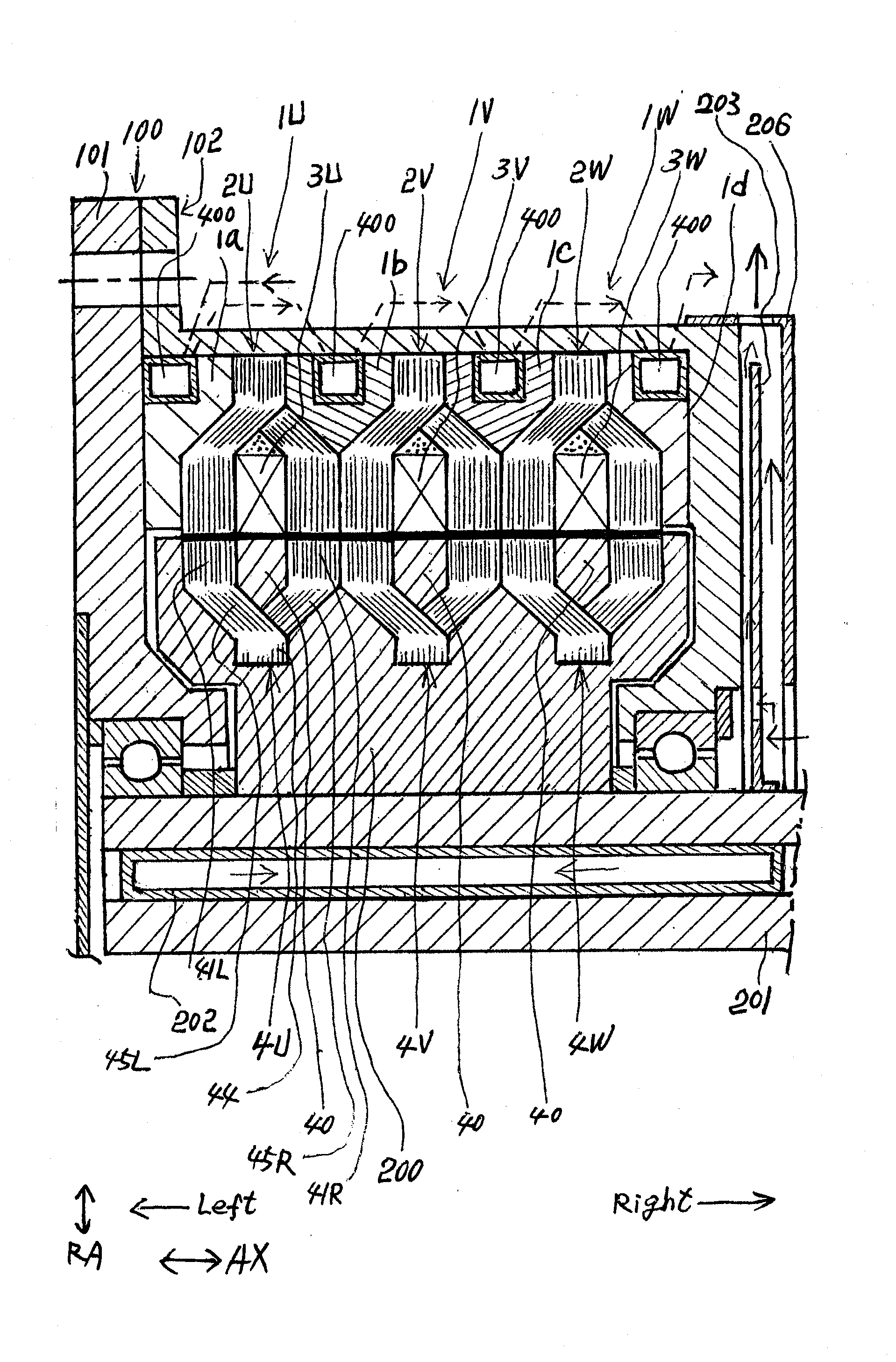
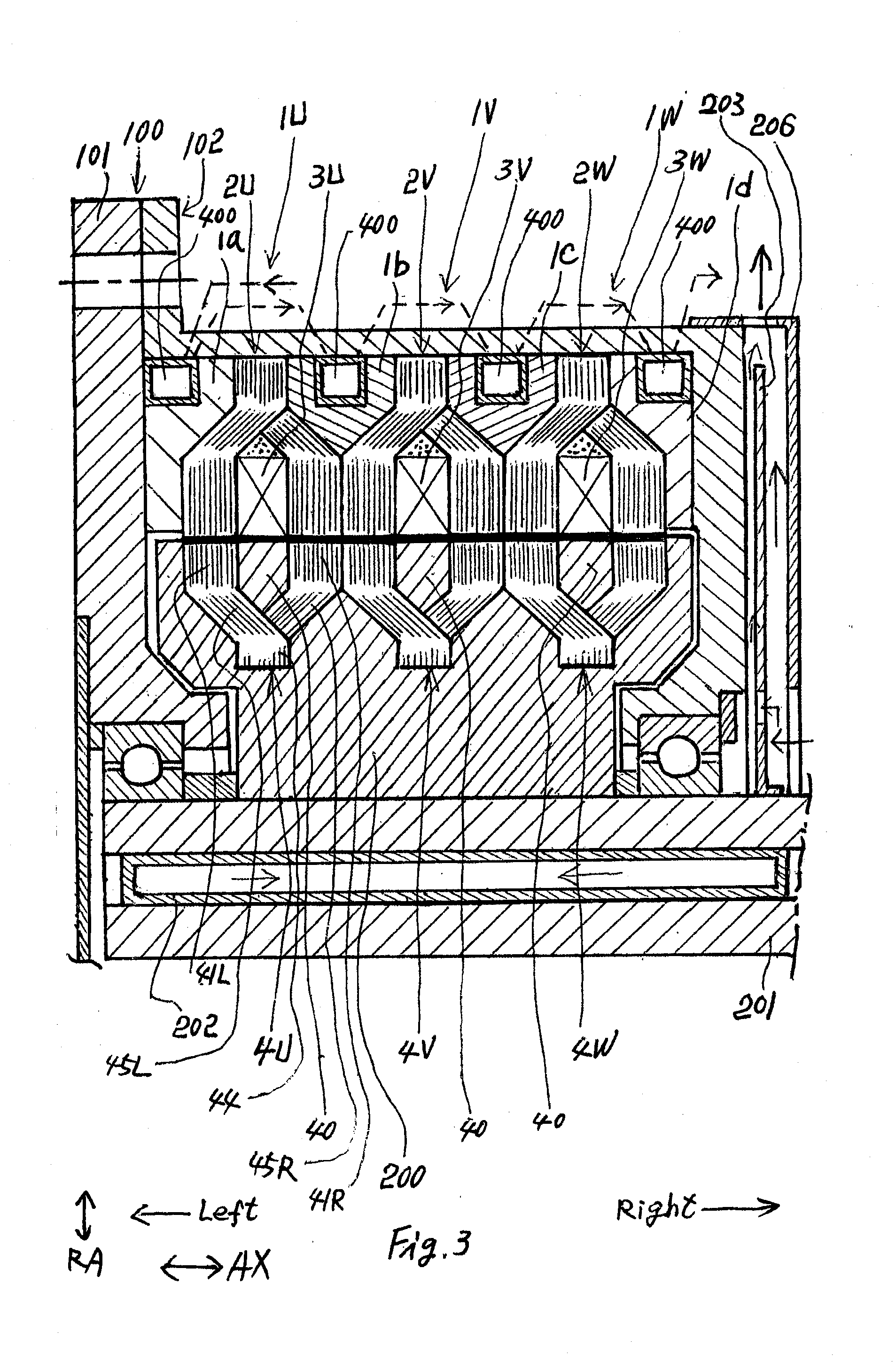
[0081]The TFMA shown in FIG. 3 has three single-phase TFIMs arranged axially in tandem. A U-phase TFIM has a U-phase stator 1U and a U-phase rotor core 4U. A V-phase TFIM has a V-phase stator 1V and a V-phase rotor core 4V. A W-phase TFIM has a W-phase stator 1W and a W-phase rotor core 4W. The stators 1U, 1V and 1W are fixed to a stator housing 100. U-phase stator 1U has a U-phase stator core 2U accommodating a U-phase winding 3U. V-phase stator 1V has a V-phase stator core 2V accommodating a V-phase winding 3V. W-phase stator 1W has a W-phase stator core 2W accommodating a W-phase winding 3W. The stator cores 2U, 2V and 2W and the phase windings 3U, 3V and 3W have ring shape each.

[0082]The stator housing 100 has a disc-shaped front housing 101 and a barrel-shaped rear housing 102. The front housing 101, a teeth-holder 1a, U-phase stator core 2U, a teeth-holder 1b, V-phase stator core 2V, a teeth-holder 1c, W-phase stator core 2W, a teeth-holder 1d and a disc po...

second embodiment

The Second Embodiment

[0100]FIG. 14 is an axial cross-section showing the TFMA having three TFWRMs (transverse flux wound-rotor machines) arranged axially in tandem. The three TFWRMs shown in FIG. 14 have field windings 6U, 6V and 6W and secondary windings 60U, 60V and 60W wound on ring-shaped spaces of rotor cores 4U, 4V and 4W. The ring-shaped spaces are formed by means of abbreviating ring portions 40 shown in FIG. 3. The ring-shaped U-phase field windings 6U and the ring-shaped U-phase secondary windings 60U are accommodated in a ring-shaped space between left teeth 41L and right teeth 41R of U-phase rotor core 4U. The ring-shaped V-phase field windings 6V and the ring-shaped V-phase secondary windings 60V are accommodated in a ring-shaped space between left teeth 41L and right teeth 41R of V-phase rotor core 4V. The ring-shaped W-phase field windings 6W and the ring-shaped W-phase secondary windings 60W are accommodated in a ring-shaped space between left teeth 41L and right tee...

third embodiment

A Third Embodiment

[0112]FIG. 28 is a schematic axial cross-section showing the tandem TFMA having three TFPMs arranged axially in tandem. Stator 1 is essentially same as stator 1 shown in FIG. 3. However, the TFPM shown in FIG. 28 does not have a rotor core 4U-4W made of iron plates. The rotor 4 shown in FIG. 28 consists of permanent magnet cylinder 600 fixed to an outer circumferential surface of non-magnetic rotor portion 605 of rotor 4. An outer circumferential surface of the permanent magnet cylinder 600 has N-pole areas 6N and S-pole areas 6S arranged alternately to the circumferential direction as shown in FIG. 29. FIG. 30 shows stator teeth 21L and 21R of stator cores 4U-4W. The rotor 4 is rotated by means of supplying the three-phase currents to three single-phase windings 3U-3W.

[0113]FIGS. 31 and 32 show magnetization process of permanent magnet cylinder 600. At first, N-pole areas N1 of odd numbered lines and S-pole areas Si of even numbered lines are magnetized as shown i...


PUM


Abstract

An object of the invention is to provide a transverse flux machine apparatus (TFMA) with simple and economical core structure. The TFMA employs a core having laminated iron plates. The core has left diagonal portions and right diagonal portions for forming the 3D flux passages. A plurality of the 3D structures employs laminated iron cores with diagonal portions. By means of employing the diagonal portions, the core looks like a centipede. The centipede-like TFM called CTFM can have a plurality of types. A plurality of motor structure and a plurality of driving means are proposed for the CTFM.

Description

CROSS-REFERENCE TO RELATED APPLICATIONS[0001]This application claims benefit under 35 U.S.C.119 of JP2012-048906 filed on Mar. 6, 2012, the title of TRANSVERSE FLUX MACHINE APPARATUS, JP2012-090672 filed on Apr. 12, 2012, the title of TRANSVERSE FLUX MACHINE APPARATUS and JP2012-95235 filed on Apr. 19, 2012, the title of TRANSVERSE FLUX MACHINE APPARATUS, the entire content of which is incorporated herein reference.BACKGROUND OF INVENTION[0002]1. Field of the Invention[0003]The present invention relates to a transverse flux machine apparatus (TFMA). More particularly, this invention relates to a transverse flux machine apparatus having a core formed with laminated iron plates.[0004]2. Description of the Related Art[0005]A transverse flux machine (TFM) with a large number of poles and short current passages is an attractive electric machine because the machine has a high torque / weight ratio, a high power / weight ratio and a low copper loss. U.S. Pat. No. 7,830,057 proposes a tandem tr...

Claims


Application Information

Patent Timeline
IPC IPC(8): H02K21/12
CPCH02K21/145H02K1/145H02K1/20H02K9/20Y02E10/725H02K16/00H02K19/10H02K2201/12H02K9/22B60L2220/12B60L2220/14B60L2220/18B60L2220/50Y02E10/72Y02T10/64H02K9/227H02K9/225
Inventor TANAKA, SHOUICHI
Owner TANAKA SHOUICHI
Why Eureka
Try Eureka