Three-phase three-level soft-switched pfc rectifiers

a pfc rectifier, three-phase technology, applied in the field of frontend rectifiers, can solve the problems of limited approaches to reduce conduction losses, and achieve the effect of reducing conduction losses and lowering voltage ratings

Active Publication Date: 2013-09-12
DELTA ELECTRONICS INC
View PDF11 Cites 55 Cited by
  • Summary
  • Abstract
  • Description
  • Claims
  • Application Information

AI Technical Summary

Benefits of technology

[0010]The present invention extends PFC and ZVS operations of the switches in the rectifier of FIG. 1 to three-l

Problems solved by technology

In power converters, achieving a high efficiency in high-voltage applications is a major design challenge that requires an optimized reduction of conduction and switching

Method used


Image

  • Three-phase three-level soft-switched pfc rectifiers
  • Three-phase three-level soft-switched pfc rectifiers
  • Three-phase three-level soft-switched pfc rectifiers

Examples


Embodiment Construction

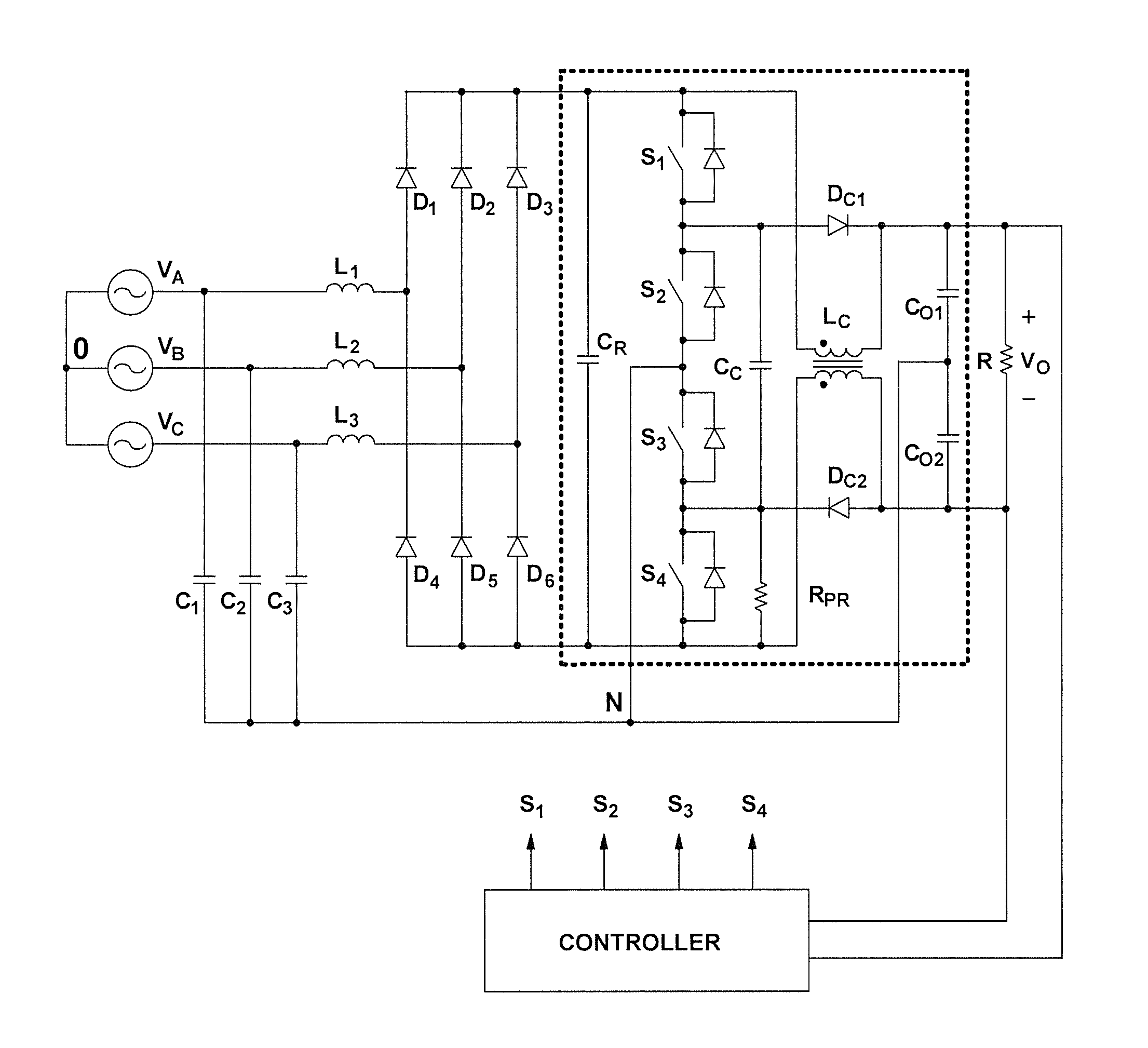
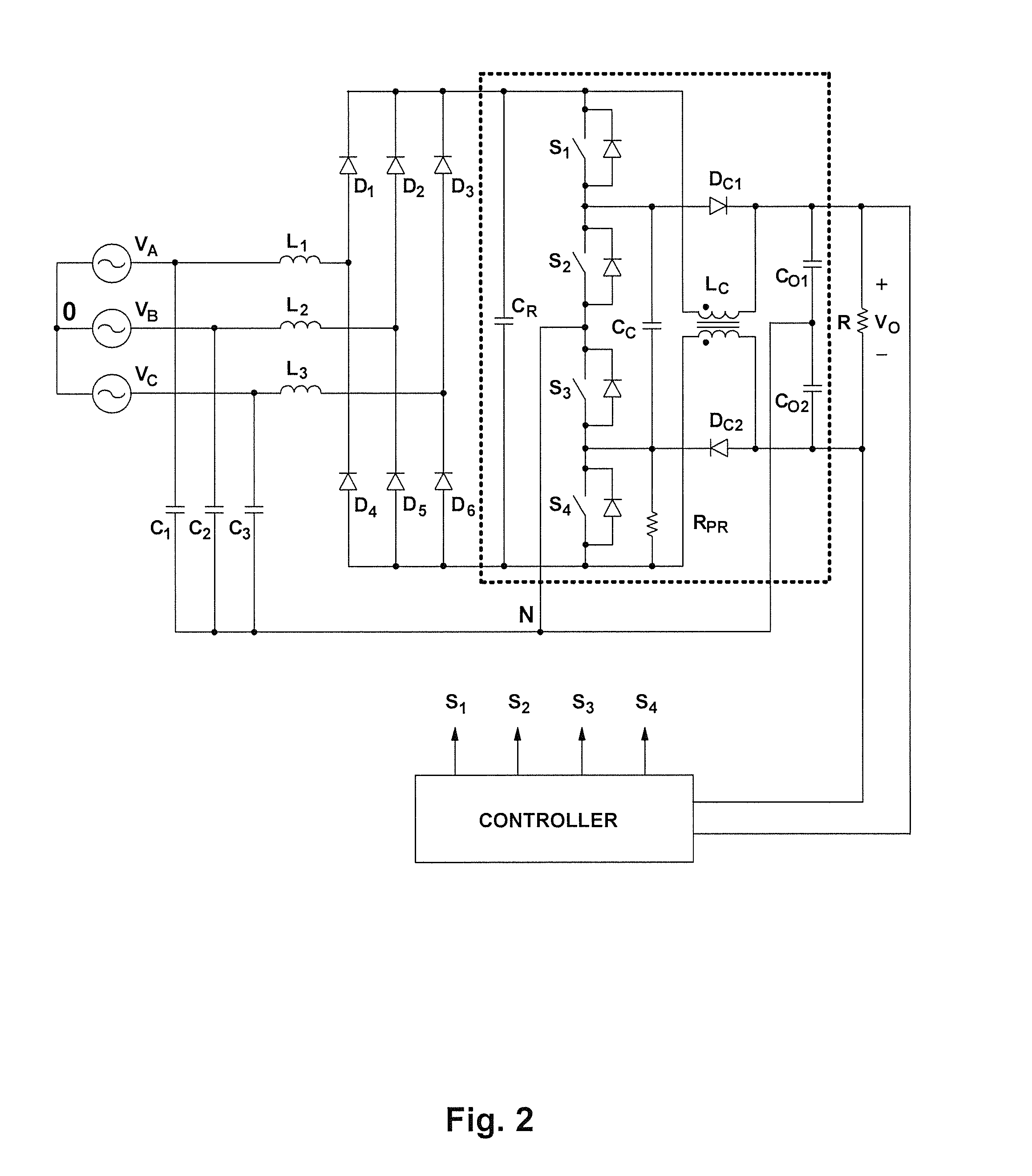
[0042]FIG. 2 is a block diagram of a three-phase, three-level ZVS PFC DCM low input-current-harmonic boost rectifier according to an embodiment of the present invention. The input stage of the circuit in FIG. 2 includes boost inductors L1, L2, and L3 coupled to capacitors C1, C2, and C3 connected in a Y (“star”) configuration. The input stage of the circuit may also include an EMI filter (not shown in FIG. 2) at the three-phase input terminals. The common node N of capacitors C1, C2, and C3 is connected to a node between serially-connected switch pairs S1-S2 and S3-S4 and also to a node between split output capacitors CO1 and CO2. The node between serially-connected switches S1-S2 is connected to output capacitor CO1 through clamping diode DC1, so that the voltage across switch S2 is clamped to the voltage across capacitor CO1, which is preferably one half of output voltage VO. The node between serially-connected switches S3-S4 is connected to output capacitor CO2 through clamping d...


PUM


Abstract

A low input-current-harmonic three-phase three-level boost rectifier includes an input stage for receiving a three-phase input voltage in relation to a neutral node and an output stage adapted to couple to at least one load. The rectifier further includes one or more switching converter stages, each having a plurality of serially-connected switches coupled to the neutral node, one of the serially-connected switches operating with a fixed duty cycle while the other of the serially-connected switches operating with a variable duty cycle, the fixed duty cycle being a substantially 50% duty cycle and the variable duty cycle being less than or equal to a substantially 50% duty cycle. The serially-connected switches are coupled to clamping diodes and clamping capacitors. The rectifier further includes one or more controllers adapted to vary the switching frequency and/or duty cycle of the plurality of switches based on at least one of a condition of the at least one load or the input voltage and includes one or more decoupling stages, each including one or more inductive elements adapted to inductively decouple the output stage from at least one of the one or more switching converter stages.

Description

CROSS REFERENCE TO RELATED APPLICATIONS[0001]The present application is a continuation-in-part of copending U.S. patent application (“Copending Application”), Ser. No. 13 / 362,620, entitled “THREE-PHASE SOFT-SWITCHED PFC RECTIFIERS,” by Jang and Jovanović, filed on Jan. 27, 2012, and assigned the attorney docket number 36977-320233. The Copending Application is hereby incorporated by reference herein in its entirety.BACKGROUND OF THE INVENTION[0002]1. Field of the Invention[0003]The present invention generally relates to front-end rectifiers with power-factor correction (PFC). In particular, the present invention relates to three-phase, three-level PFC rectifiers.[0004]2. Discussion of the Related Art[0005]In power converters, achieving a high efficiency in high-voltage applications is a major design challenge that requires an optimized reduction of conduction and switching losses through a careful selection of the converter topology and switching device characteristics. Specifically...

Claims


Application Information

Patent Timeline
IPC IPC(8): H02M5/458
CPCH02M1/4216H02M7/23Y02B70/126H02M7/217H02M5/4585Y02B70/10Y02P80/10H02M1/123
Inventor JANG, YUNGTAEKJOVANOVIC, MILAN M.
Owner DELTA ELECTRONICS INC
Why Eureka
Try Eureka