MIMO antenna calibration device, integrated circuit and method for compensating phase mismatch

a technology of phase mismatch and antenna calibration, which is applied in the direction of polarisation/directional diversity, transmission, synchronous/start-stop systems, etc., can solve the problems of insufficient space for extra antennas, many sites are crowded, and the capacity and coverage of many sites are difficult to achieve, so as to reduce the number of sites and eliminate the problem of one or more.

Active Publication Date: 2013-09-12
ANALOG DEVICES INT UNLTD
View PDF8 Cites 61 Cited by
  • Summary
  • Abstract
  • Description
  • Claims
  • Application Information

AI Technical Summary

Benefits of technology

[0023]Accordingly, the invention seeks to mitigate, alleviate or eliminat...

Problems solved by technology

Recent trials in HSPA+ networks have uncovered a problem with capacity and coverage issues with single antenna UE (User Equipment) devices.
Furthermore, many sites are crowded and room for extra antennae is not available.
Many current UEs, will not support new upgrades to the 3G standard and are therefore unable to utilise HSPA+.
In particular, recent trials of HSPA+ networks have uncovered a problem due to a use of linear polarisation (LP) transmission diversity and its effects on 3G UE devices that do not have the capability of diversity reception.
A UE device supporting only older versions of the standard may only have one receive antenna and, thus, will not be able to exploit the transmission diversity of the upgraded network.
A problem arises as the LP antenna UE device is rotated or moved to a location where the second orthogonal transmission from the MIMO enabled Node B becomes much stronger than the desired first orthogonal transmission.
Furthermore, the second orthogonal transmission signal remains as an uncorrelated interferer as such a UE device is not able to process both MIMO transmissions at the same time.
The received carrier to interference plus noise ratio (CINR) may degrade the receiver performance by 10's of dBs, thereby causing communication links to be dropped and consequently reducing cell coverage area.
However, in practical systems there will be minor deviations from this perfect angular electric field vector that describes a circle.
A known problem in using LP transmissions is that the polarisation of the transmitted signal antenna and the receiving signal antenna (if also an LP type) needs to have the angle of polarisation exactly the same for reception of the strongest signal.
As a polarised signal may deviate from its ideal 90° difference, then the polarisation diversity benefits deteriorate quickly to an elliptical type polarisation, thus greatly affecting the performance of communications in the network.
The resultant phase imbalance may be accumulated at multiple sources, which include for example, cable feeds, transmitter chains, phase locked loops (PLLs), duplexers, etc.
Simple ...

Method used


Image

  • MIMO antenna calibration device, integrated circuit and method for compensating phase mismatch
  • MIMO antenna calibration device, integrated circuit and method for compensating phase mismatch
  • MIMO antenna calibration device, integrated circuit and method for compensating phase mismatch

Examples


Embodiment Construction

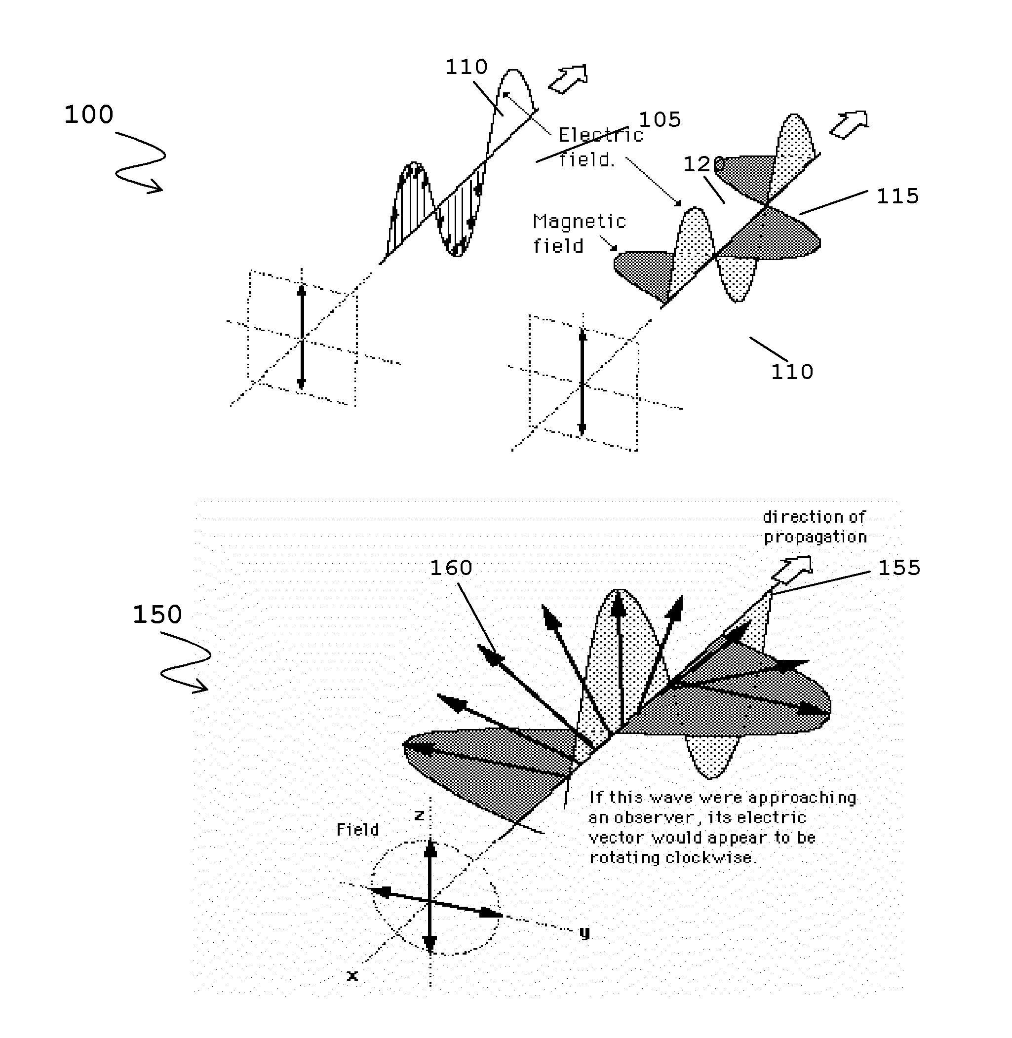
[0059]In the described examples, a reference to a native polarisation of an antenna encompasses the polarisation of a signal processed by one antenna element acting independently of at least one other antenna element. In the XPOL (cross polarisation) example cited heretofore the native polarisation would be LP (linear Polarised) +45° and LP −45°. Independent signals processed by these antenna elements will undergo no polarisation transformation. When a modified version of the same signal is processed concurrently in antenna elements of both polarisations, and through combining forms a different polarisation type, then this is referred to as non-native.

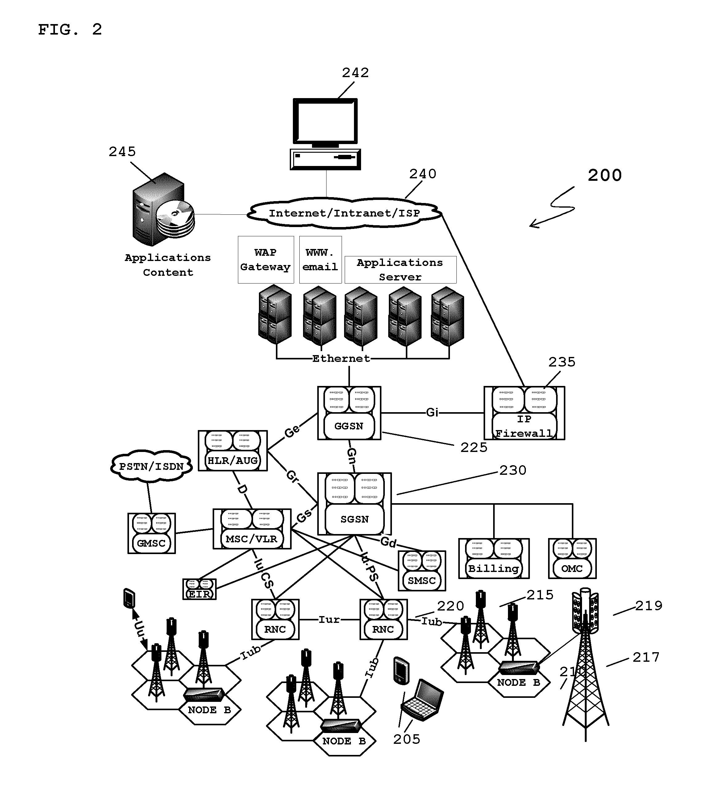
[0060]The term ‘MIMO’, as defined herein, encompasses a multiple input multiple output communications system where at least two spatially or polarization diverse antennas for both receive and transmit are used on at least one end of a communications link.

[0061]It is well known that the cable feed between an antenna array and a NodeB wi...


PUM


Abstract

A multiple input multiple output (MIMO) calibration device (360) for calibrating a phase relationship between at least two signals present on at least two radio frequency (RF) paths coupling a wireless communication unit and the MIMO calibration device (360) is described. The MIMO calibration device (360) is operably coupleable via at least two RF paths between a wireless communication unit and an antenna arrangement (219). The calibration device (360) comprises a processing module (490) configured to: process a coupled amount of at least one first signal from a first path operably coupleable to a first polarisation of the antenna arrangement (219) to determine at least one pilot signal from said at least one first signal; process a coupled amount of at least one second signal from a second path operably coupleable to at least one second polarisation feed of antenna arrangement (219), different to the first polarisation, to determine the at least one pilot signal from said at least one second signal; and determine a first phase relationship of the same pilot signal between the at least two RF paths.

Description

FIELD OF THE INVENTION[0001]The field of the invention relates to an apparatus and a method for calibrating a phase relationship and compensating for phase mismatch on feeds to an antenna arrangement and, in particular an apparatus and method for calibrating and compensating phase mismatch to control radiated signal polarisation.BACKGROUND OF THE INVENTION[0002]Conventional antenna arrays, as used in cellular infrastructure macro cells, comprising multiple antenna elements and used with existing Node-B equipment in most third generation (3G) installations, utilise a fixed 65° beam pattern. Outside of the main lobe of the antenna beam the signals are spatially filtered and significantly attenuated. Conventional network planning and passive antenna array solutions process all incoming signals with a common fixed beam pattern. Such receive processing, based on signals received within the geographic area identified by the antenna beam main lobe, referred to as the RF footprint, tends to...

Claims


Application Information

Patent Timeline
IPC IPC(8): H04L7/00
CPCH01Q3/267H04B7/10H04B17/21H04B17/12H04L7/0016H01Q3/26
Inventor O'KEEFE, CONORO'BRIEN, MICHAEL
Owner ANALOG DEVICES INT UNLTD
Why Eureka
Try Eureka