Universal dental implant structure

a dental implant and universal technology, applied in dental implants, dental surgery, medical science, etc., can solve the problems of occlusion interference easily, implantation failure, strength deficiency of bone integration, etc., to avoid grinding adjustment, prevent inadequate bone integration strength, and avoid grinding adjustment.

Inactive Publication Date: 2013-09-12
LIN YEN CHANG
View PDF0 Cites 4 Cited by
  • Summary
  • Abstract
  • Description
  • Claims
  • Application Information

AI Technical Summary

Benefits of technology

[0011]1. With the extended holding portion extended outside the cortical bone between merely 3 mm and 6 mm the problem of occlusion interference during bone integration can be averted and inadequate bone integration strength can be prevented.
[0012]2. Compared with the conventional technique of extending the implant member outside the cortical bone about at least 10 mm, the invention extends the implant member by 3 mm to 6 mm, thus is avoided performing the grinding adjustment caused by inadequate occlusion space between the upper teeth and lower teeth and the problems of time-consuming and effort-wasting.
[0013]3. In the event that the occlusion space is insufficient, the tooth cap and implant member can be coupled to get the advantage of the one-piece dental implant structure. On the other hand, when the occlusion space is greater, an abutment can be used to fasten to the coupling cavity of the implant member to achieve the advantage of the two-piece dental implant structure with the flexibility of changing shape and size of the abutment. Thereby it is adaptable to one-piece type and two-piece type structure.
[0014]4. The dentist requires preparing merely the implant member with the same specification to meet the requirements of different patients, thus usability improves.

Problems solved by technology

But it also has a drawback, i.e., as the one-piece type implant member is extended outside the cortical bone about 10 mm, occlusion interference easily takes place when chewing of the patient during the bone integration period.
This could result in strength deficiency of the bone integration and affect the sturdiness after implantation, and the bone could be atrophied to result in implantation failure.
Moreover, the one-piece type implant member cannot be coupled with other tooth cap, the design space and types of the denture also are limited.
Such an approach has the advantage of eliminating the occlusion interference and making diversified designs of the crown possible to mate different types of tooth caps; however, it also has a drawback, i.e. the implant member must be precisely fastened and leveled on the cortical bone to facilitate coupling of the crown in the later process.
As uncertainty still cannot be totally eliminated in medical clinics, if the implant member is implanted too deep into the cortical bone, it will be slightly covered by the cortical bone during bone integration period to result in difficulty of coupling with the crown in the later process.
Another drawback is having weaker structural strength.
Since the crown is mostly fastened to the implant member by screwing and positioned in the soft tissue, its horizontal bracing force also is insufficient.
Thus when the crown is subject to a horizontal shearing force, the screw fastening structure could be easily fractured.
In the event that such an incident happens, the residual screw fastener still remains in the implant member to cause removing and repair difficult.
It is troublesome in use.
Moreover, a dentist has to prepare one-piece implant structure and two-piece implant structure to meet requirements of different patients, and they cannot be interchanged.
Moreover, because the implant member 2 has multiple screw threads formed on the surface thereof, the exposed screw threads could breed microbes and cause ailments.
To prevent exposure of the screw threads, additional fabrication processes are needed that are time-consuming and costly.
Also referring to FIG. 1B, if the implant member 2 is implanted too depth into the gum 1, mounting of the abutment in the later process could be difficult.

Method used


Image

  • Universal dental implant structure
  • Universal dental implant structure
  • Universal dental implant structure

Examples


Embodiment Construction

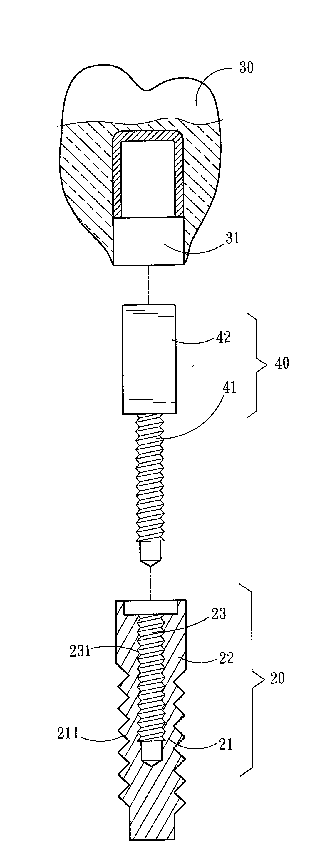
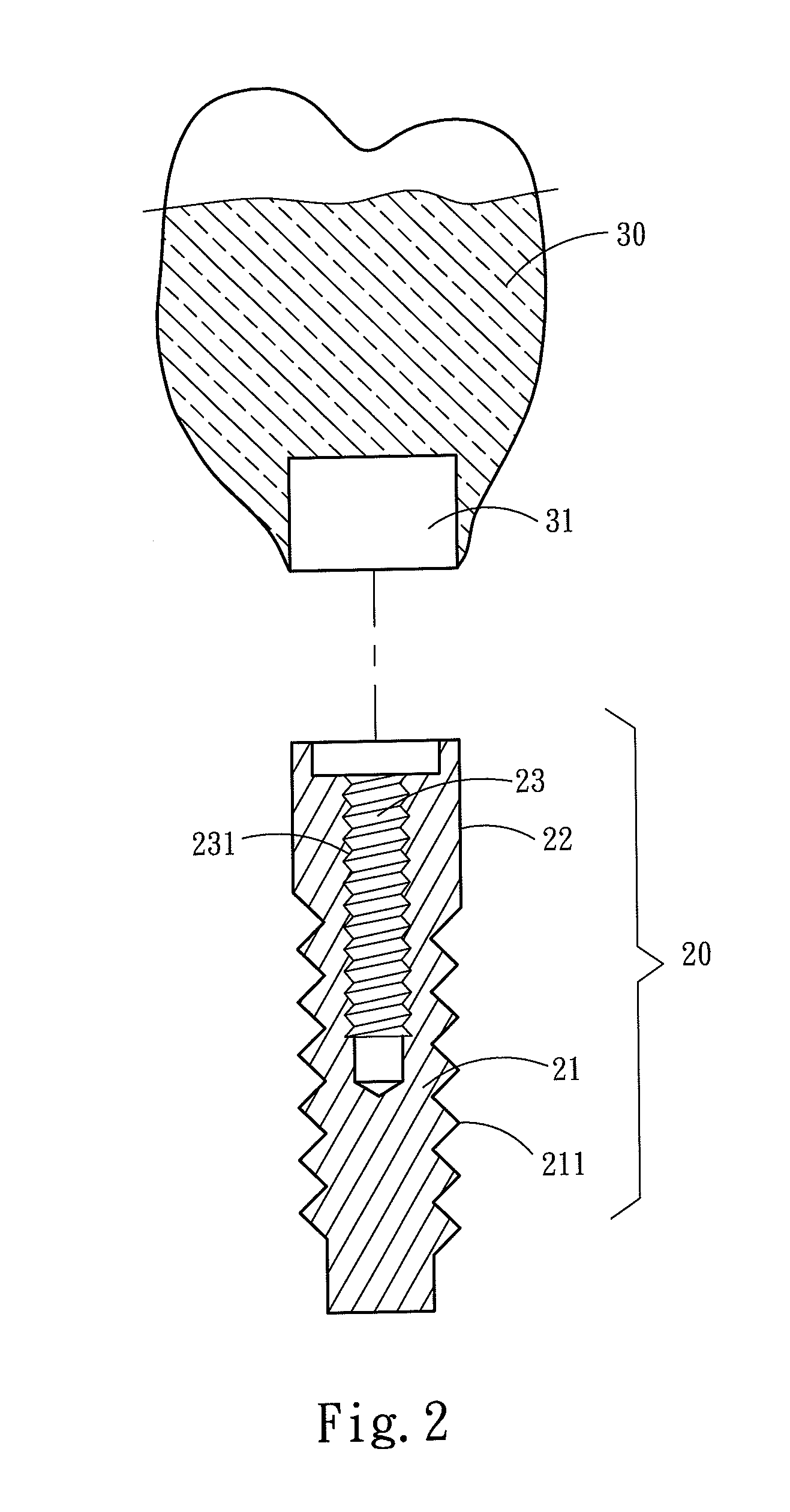
[0029]Please refer to FIGS. 2 and 4A, the present invention aims to provide a universal dental implant structure implanted in a patient's gum 10. The gum 10 has a cancellous bone 11, a cortical bone 12 located on the surface of the cancellous bone 11 and a soft tissue 13 located at one side of the cortical bone 12 remote from the cancellous bone 11. The universal dental implant structure includes an implant member 20 and a tooth cap 30. The implant member 20 has an implant portion 21, an extended holding portion 22 connecting to the implant portion 21 and a coupling cavity 23 located on one side of the extended holding portion 22 remote from the implant portion 21. The coupling cavity 23 is extended from the extended holding portion 22 towards the implant portion 21 and has an internal thread section 231 on an inner surface thereof. The tooth cap 30 has a coupling portion 31 to encase and fasten to the extended holding portion 22.

[0030]In the event that the dental implant is done on...


PUM


Abstract

A universal dental implant structure includes an implant member and a tooth cap. The implant member has an implant portion, an extended holding portion connecting to the implant portion and a coupling cavity located at one side of the extended holding portion remote from the implant portion. The implant portion is anchored in a cancellous bone and a cortical bone. The extended holding portion is extended outside the cortical bone in a range between 3 mm and 6 mm. The tooth cap has a coupling portion to couple on and fasten to the extended holding portion. The dental implant structure of the invention resolves the problem of occlusion interference in the conventional one-piece type dental implant structure and provides the advantage of withstanding high shearing force thereof, and also has the advantage of flexible assembly in the two-piece type dental implant structure through an abutment.

Description

FIELD OF THE INVENTION[0001]The present invention relates to a dental implant structure and particularly to a universal dental implant structure.BACKGROUND OF THE INVENTION[0002]The technology of dental implant is well developed now. Dental implant is performed first by implanting an implant made of titanium that has high bio-compatibility into an alveolus for positioning. After few months when the implant has been firmly fastened to the bone in the alveolus, a denture is mounted. As the implant is directly connected to the bone, a desired support force can be provided for chewing harder foods. Thus it is widely accepted. The conventional dental implant includes an implant member which can be categorized into a one-piece type and a multi-piece type. The one-piece type implant member, such as U.S. publication No. 2010 / 0119993 entitled “Dental implant” is to directly implant the one-piece type implant member into the cancellous bone and cortical bone of the gum. After few months when ...

Claims


Application Information

Patent Timeline
Patent Type & Authority Applications(United States)
IPC IPC(8): A61C8/00
CPCA61C8/0018A61C8/0075A61C8/0068A61C8/0048
Inventor LIN, YEN-CHANG
Owner LIN YEN CHANG
Why Eureka
Try Eureka