Hydraulic hybrid vehicle

Active Publication Date: 2013-09-19
HONDA MOTOR CO LTD
View PDF4 Cites 10 Cited by
  • Summary
  • Abstract
  • Description
  • Claims
  • Application Information

AI Technical Summary

Benefits of technology

[0008]The present invention has been made in view of the above-mentioned circumstances. An object of the present invention is to achieve a reduct

Problems solved by technology

Incidentally, when such hydraulic hybrid vehicles include a power train formed of the engine and the transmission, an oil tank and a pump motor for a hydraulic hybrid system are necessary in addition to an oil pan and an oil pump for supplying hydraulic

Method used


Image

  • Hydraulic hybrid vehicle
  • Hydraulic hybrid vehicle
  • Hydraulic hybrid vehicle

Examples


first embodiment

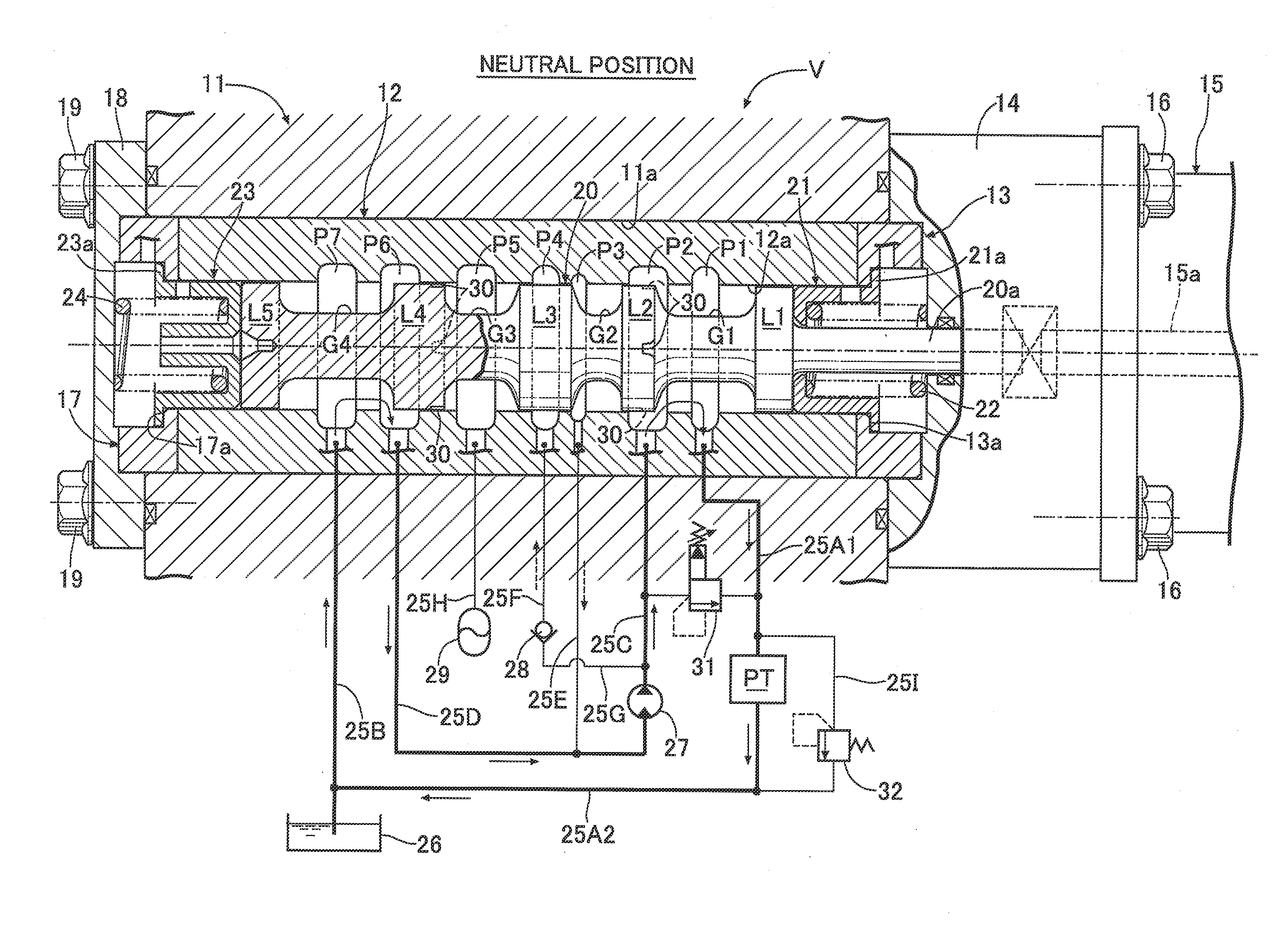
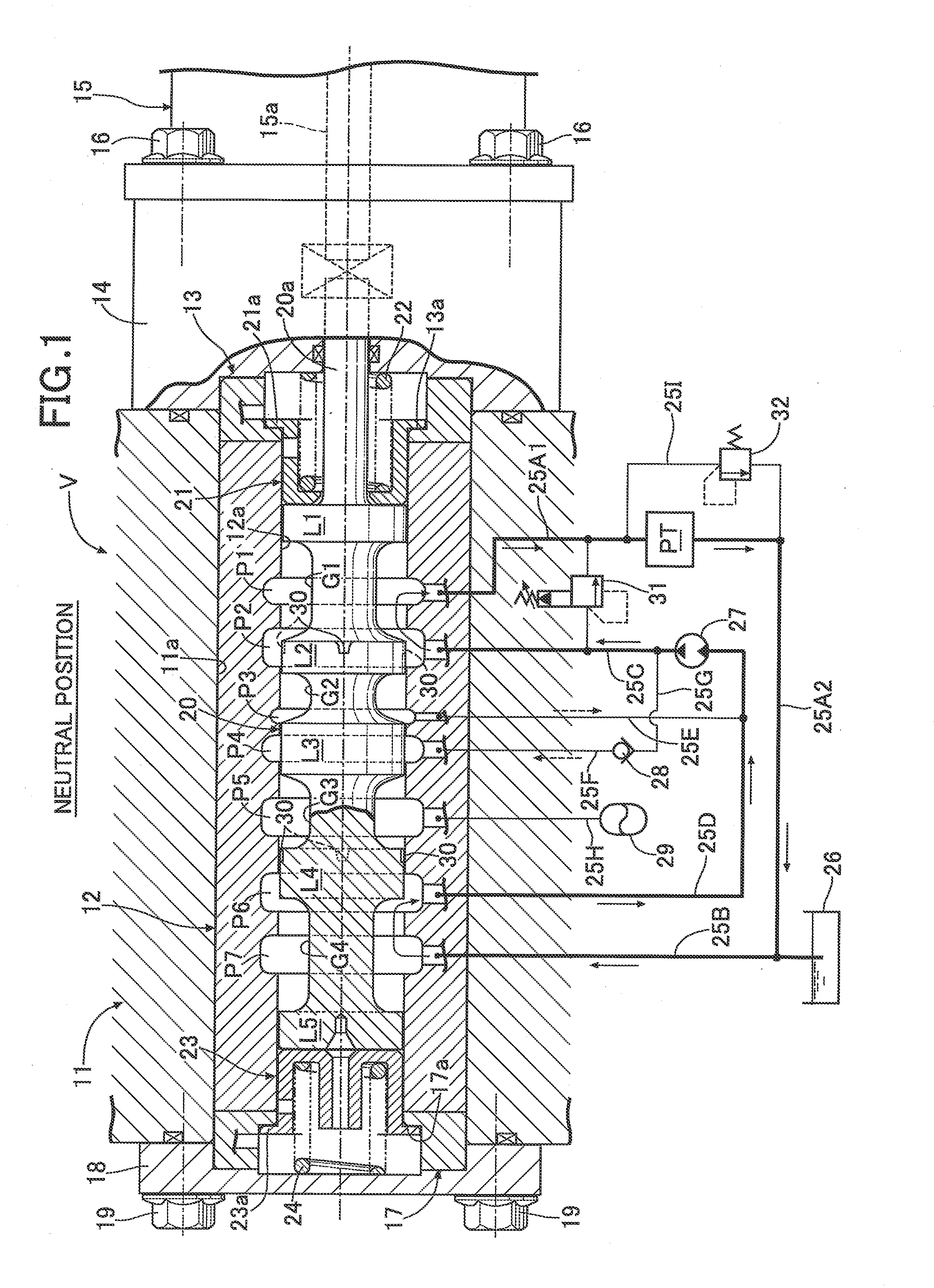
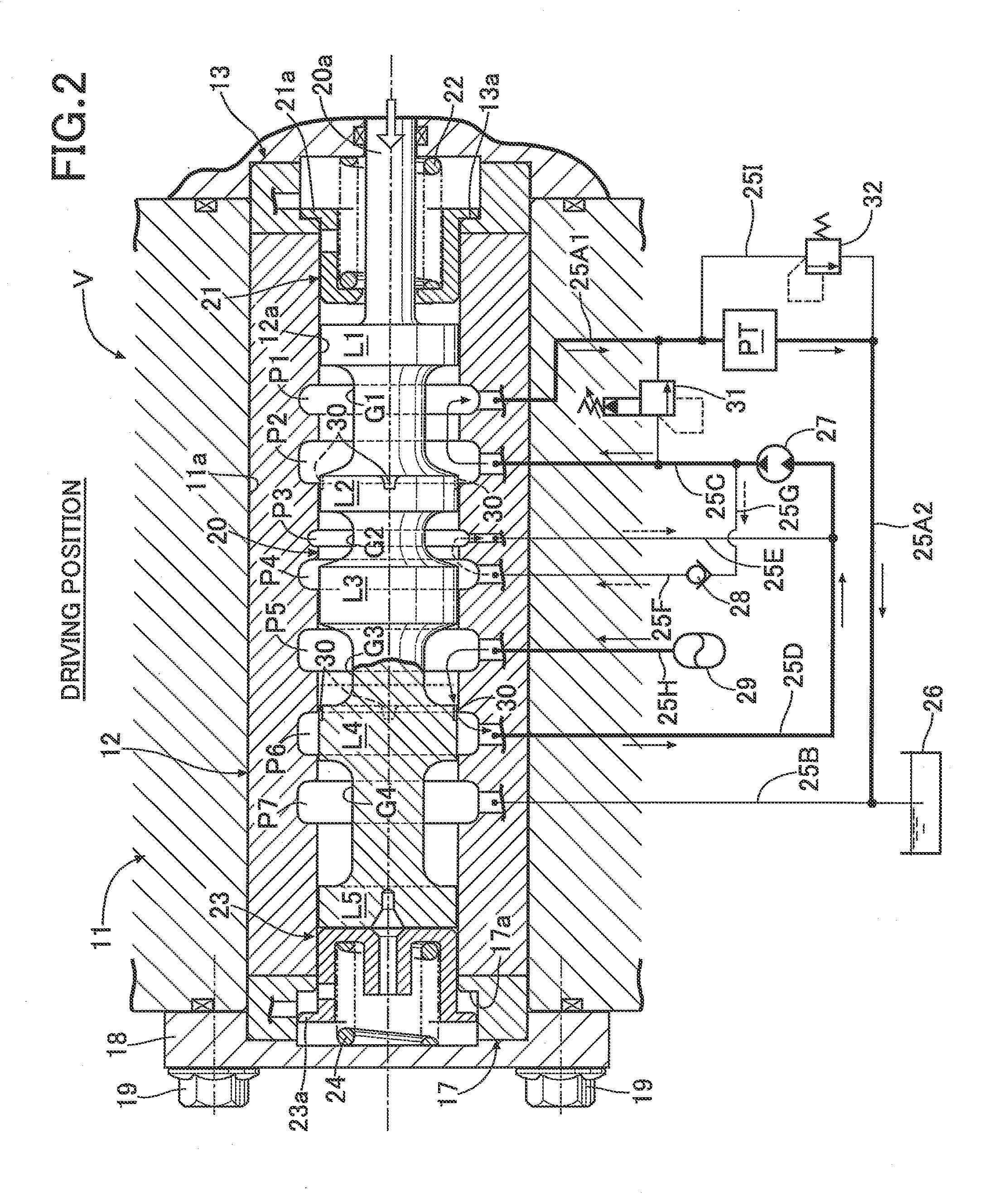
[0053]the present invention will be described below with reference to FIGS. 1 to 5.

[0054]As illustrated in FIG. 1, a spool valve V for use in a hydraulic hybrid system for an automobile is provided with a cylindrical sleeve 12 fitted in a sleeve supporting hole 11a formed in a valve case 11, and a solenoid supporting member 14 covering an outer surface of an annular first end plate 13 which abuts against one end of the sleeve 12 is fastened together with a linear solenoid 15 to one side surface of the valve case 11 by plural bolts 16, and a cover member 18 covering an outer surface of an annular second end plate 17 which abuts against the other end of the sleeve 12 is fastened to the other side surface of the valve case 11 by plural bolts 19. A spool 20 is axially slidably fitted within a spool hole 12a formed in the sleeve 12, and a tip end of a rod portion 20a extending from one end of the spool 20 and a tip end of an output rod 15a of the linear solenoid 15 are connected together...


PUM


Abstract

A pump motor of a hydraulic hybrid system also serves as a pump to supply hydraulic oil or lubricating oil to a power train, thus enabling elimination of an oil pump provided in the power train and hence reductions in the number of parts and cost, and, in addition, an existing oil pan provided in the power train and the like are utilized for the hydraulic hybrid system, which in turn enables achieving further reductions in the number of parts and cost. Moreover, when idle-reduction control is performed on an engine, during engine's stopped conditions, the pump motor can be driven as a motor by hydraulic pressure accumulated in an accumulator to start the engine and supply the hydraulic pressure to a transmission, thus eliminating a need to provide a motor-driven oil pump for the idle-reduction control and hence enabling a further reduction in cost.

Description

CROSS-REFERENCE TO RELATED APPLICATIONS[0001]The present application claims priority under 35 USC 119 to Japanese Patent Application Nos. 2012-56805, 2012-56807 and 2012-56808 filed on Mar. 14, 2012 the entire contents of which are hereby incorporated by reference.BACKGROUND OF THE INVENTION[0002]1. Field of the Invention[0003]The present invention relates to a hydraulic hybrid vehicle comprising: a power train including an engine and a transmission; a pump motor; and an accumulator, wherein the pump motor is driven as a motor by hydraulic pressure accumulated in the accumulator to effect travel of the vehicle, to assist the engine, or to start the engine, and the pump motor is driven as a pump by drive power from the engine or by drive power transmitted back from a drive wheel to accumulate pressure in the accumulator.[0004]2. Description of the Related Art[0005]Japanese Patent Application Laid-open No. 8-282324 has made known a hydraulic hybrid vehicle in which an engine is connec...

Claims


Application Information

Patent Timeline
IPC IPC(8): F15B1/04
CPCB60K6/12Y02T10/6208F15B1/04F15B1/024Y02T10/62
Inventor ISHIKAWA, SEIICHIROKIMURA, YASUNARIKATO, MASASHISATO, DAIKISHIBAHATA, YUKI
Owner HONDA MOTOR CO LTD
Why Eureka
Try Eureka