Stirling cycle transducer apparatus

a transducer and cycle technology, applied in the field of transducers, can solve the problems of high temperature material cost, affecting the adoption of stirling engines, and difficulty in making high pressure and high temperature reciprocating or rotating gas seals, so as to minimize the loss in the communication passage, increase the efficiency of the transmission channel, and improve the effect of thermal energy exchang

Active Publication Date: 2013-09-19
ETALIM
View PDF12 Cites 5 Cited by
  • Summary
  • Abstract
  • Description
  • Claims
  • Application Information

AI Technical Summary

Benefits of technology

[0014]The regenerator may have a length that is less than a spacing between the expansion chamber and the compression chamber along the longitudinal axis and the regenerator length may be selected to enhance thermal energy exchange with gas flowing through the regenerator while minimizing losses due to flow friction through the regenerator and the access conduit may be configured to span a remaining portion of the spacing between the expansion chamber and the compression chamber.
[0015]The spacing between the expansion chamber and the compression chamber may be selected such that combined losses due to thermal conduction between the...

Problems solved by technology

The adoption of Stirling engines has been hampered in part by the cost of high temperature materials, and the difficulty of making high pressure and high temperature reciprocating or rotating gas seals.
Furthermore the need for relatively large heat exchangers and low specific power in comparison to internal combustion engines has also hampered widespread adoption of Stirling engines.
Specific power refers to output power per unit of mass, volume or area an...

Method used


Image

  • Stirling cycle transducer apparatus
  • Stirling cycle transducer apparatus
  • Stirling cycle transducer apparatus

Examples


Embodiment Construction

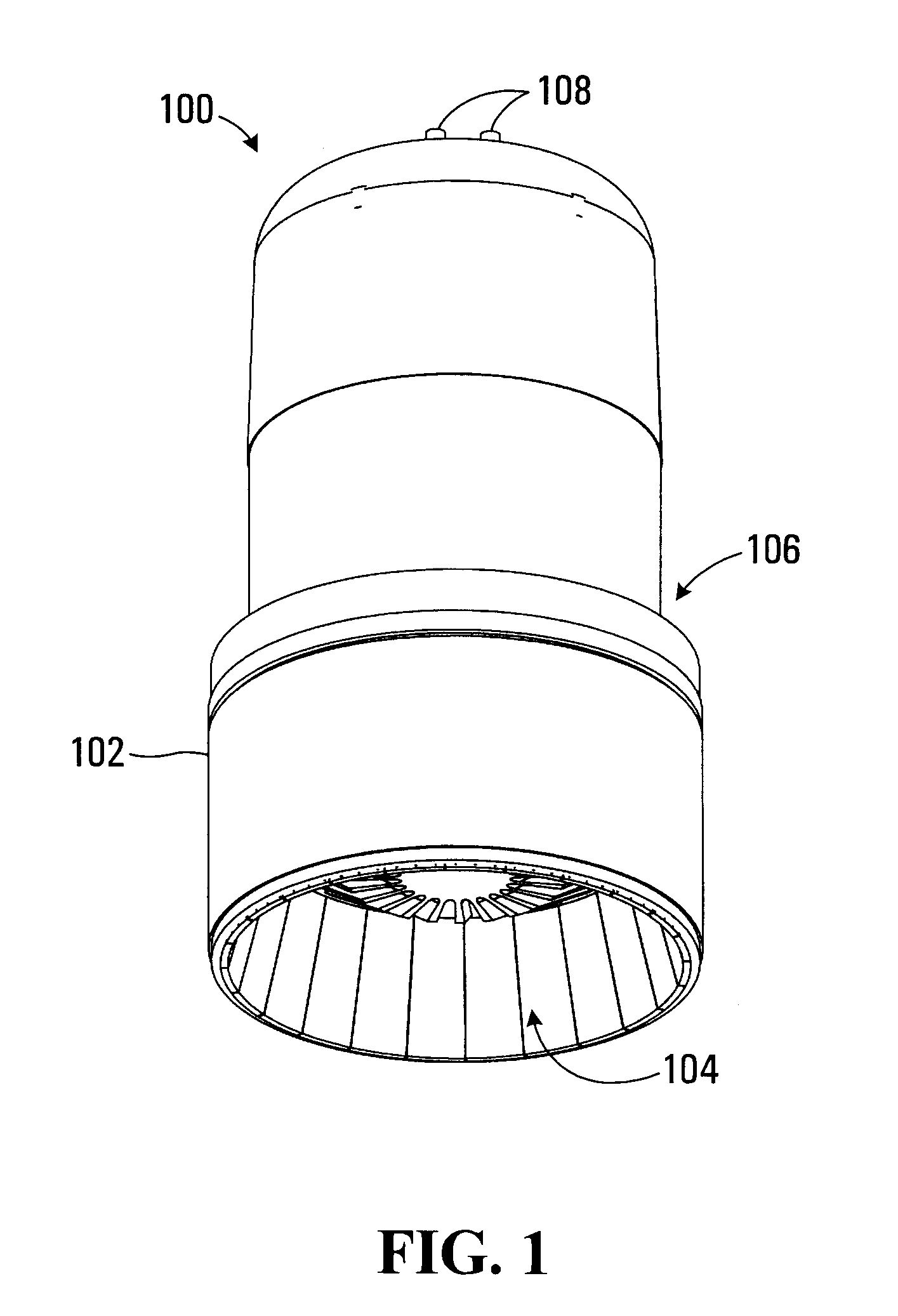
[0085]Referring to FIG. 1, a Stirling cycle transducer apparatus for converting between thermal energy and mechanical energy is shown generally at 100. The apparatus 100 includes a housing 102, which encloses components of the apparatus that define a hot side 104 and a cold side 106 of the Stirling cycle transducer. The apparatus 100 further includes a pair of electrical terminals 108 providing for an electrical connection to the apparatus 100.

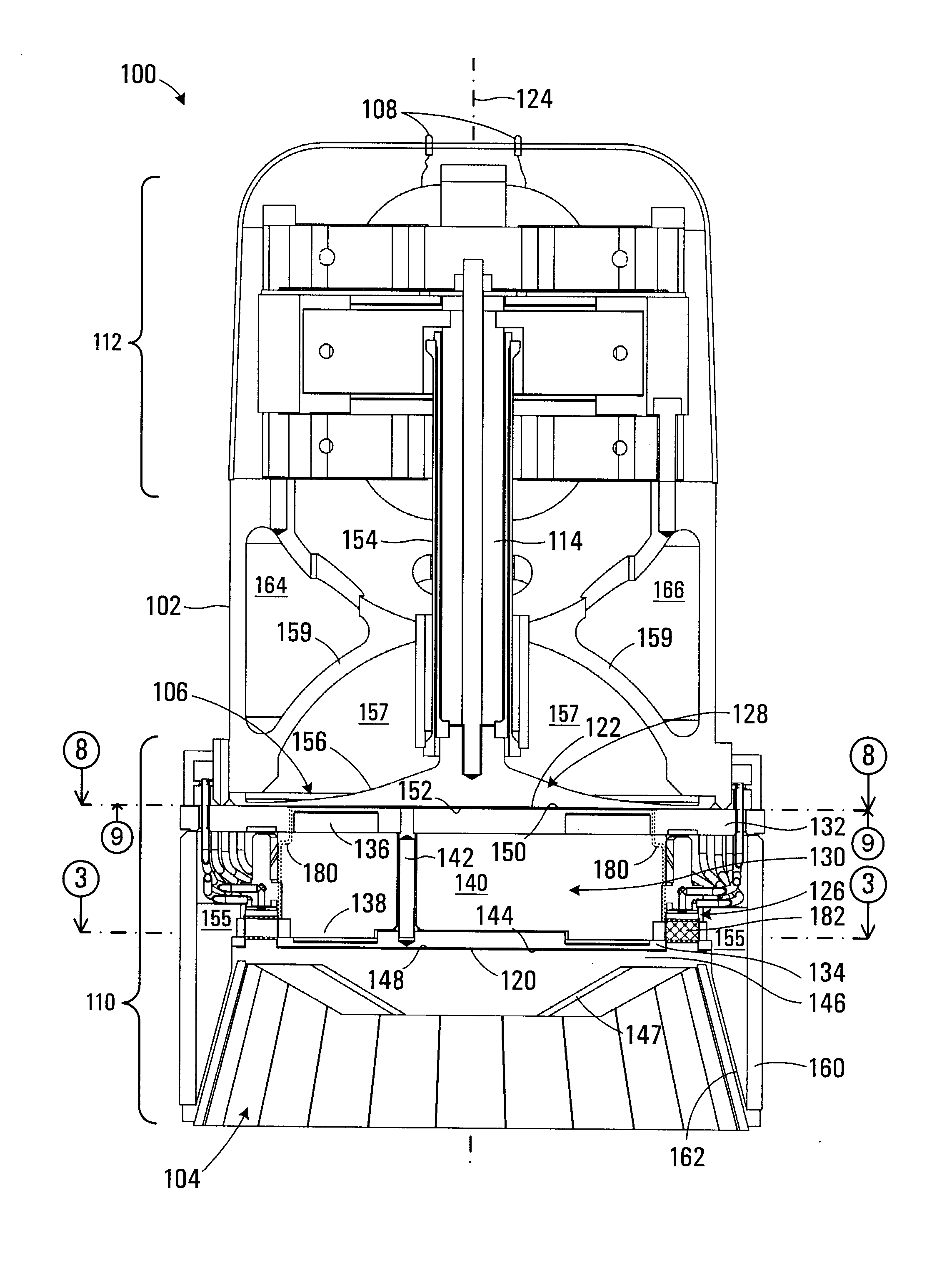
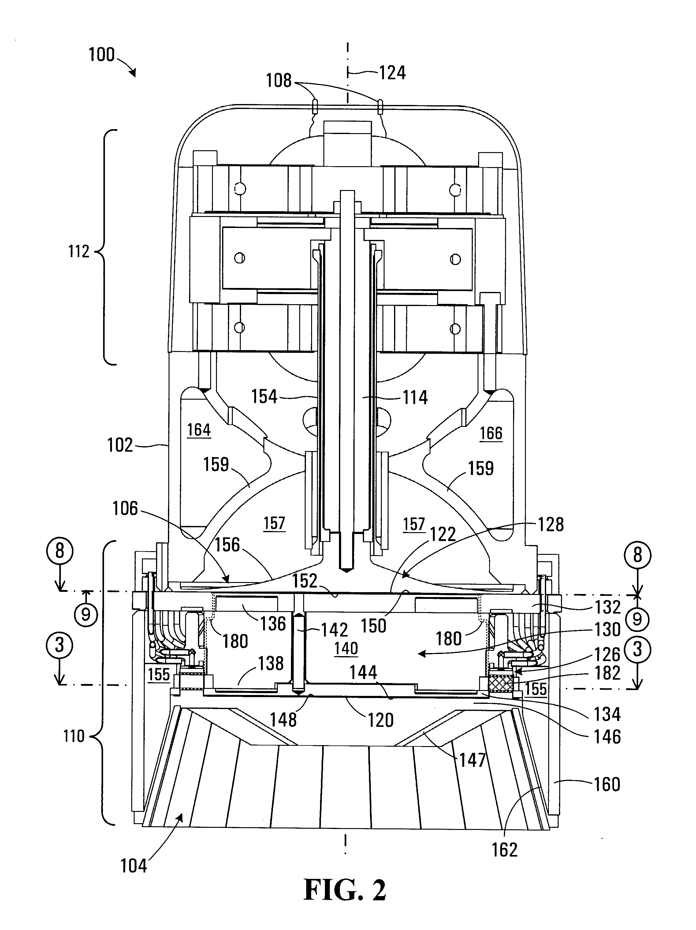
[0086]The apparatus 100 is shown in cross sectional detail in FIG. 2. In the embodiment shown the apparatus 100 is configured to operate as an engine and includes a Stirling cycle transducer portion 110 and an electrical generator portion 112. The transducer portion 110 is mechanically coupled to the generator portion 112 by a drive rod 114 and the generator is electrically connected to the electrical terminals 108. In operation of the apparatus 100 as an engine, thermal energy is received at the hot side 104 and converted by the transducer po...


PUM


Abstract

A communication passage in a Stirling cycle transducer includes a cylindrical shaped thermal regenerator providing flow paths aligned with a regenerator cylindrical axis for providing periodic gas flow between first and second interfaces of the regenerator. A first heat exchanger conveys gas between a periphery of the heat exchanger and the first interface causing a change of direction of gas flow between radially and axially oriented flow within the regenerator and transfers heat between the gas and an external environment in a direction aligned with the regenerator cylindrical axis. A second heat exchanger conveys gas between a periphery of the heat exchanger and the second interface causing a change of direction of gas flow between radially and axially oriented flow within the regenerator and transfers heat between the external environment and the gas in a direction aligned with the regenerator cylindrical axis.

Description

CROSS REFERENCE TO RELATED APPLICATIONS[0001]This application claims the benefit of the filing date of U.S. Provisional Application 61 / 415,196 entitled “STIRLING CYCLE TRANSDUCER APPARATUS” filed on Nov. 18, 2010 by Thomas Walter Steiner, Briac Medard de Chardon, and Takao Kanemaru and which is incorporated herein by reference in it's entirety.BACKGROUND OF THE INVENTION[0002]1. Field of Invention[0003]This invention relates generally to transducers and more particularly to a Stirling cycle transducer for converting thermal energy into mechanical energy or for converting mechanical energy into thermal energy.[0004]2. Description of Related Art[0005]Stirling cycle heat engines and heat pumps date back to 1816 and have been produced in many different configurations. Potential advantages of such Stirling cycle devices include high efficiency and high reliability. The adoption of Stirling engines has been hampered in part by the cost of high temperature materials, and the difficulty of ...

Claims


Application Information

Patent Timeline
IPC IPC(8): F02G1/057F02G1/053
CPCF02G1/043F02G1/053F02G1/057F02G2257/00
Inventor STEINER, THOMAS WALTERMEDARD DE CHARDON, BRIACKANEMARU, TAKAO
Owner ETALIM
Why Eureka
Try Eureka