Winding glass ribbon by tensioning interleaving material

a technology of interleaving material and winding method, which is applied in the direction of manufacturing tools, transportation and packaging, synthetic resin layered products, etc., can solve the problems of risking damage to glass ribbon, not advisable to have direct surface to surface contact of glass to itself, and extremely sensitive to surface defects, etc., to achieve better handling, better density of rolled products, and better storage

Active Publication Date: 2013-09-19
CORNING INC
View PDF3 Cites 16 Cited by
  • Summary
  • Abstract
  • Description
  • Claims
  • Application Information

AI Technical Summary

Benefits of technology

[0009]More specifically, the inventors found that typical web winding process parameters of 1-2 pounds per linear inch of web tension, and 15-50 pounds per square inch of pressure between the layers, when used with a thin glass ribbon and interleaving material produced angled side walls in the roll. Further, contrary to conventional wisdom (which dictates using high tensions and inter-layer pressures to achieve better handling, better storage, and better density of rolled product), the inventors found that increasing the web tension and pressure between the layers of glass ribbon and interleaving material actually made the side wall characteristics worse. Surprisingly, the inventors found that using lower web tension and lower pressure between the layers produced straighter side walls in the roll. More particularly, a web tension of greater than 0 pounds per linear inch, but 0.25 pounds per linear inch or less (0.3 kg / cm or less), and a pressure between the layers in the roll of 10 pounds per square inch or less (0.07 MPa or less), but greater than 0 pounds per square inch, produced straight side walls on the rolled thin glass. In another embodiment, pressure between the layers in the roll of 7 pounds per square inch or less (0.05 MPa or less), but greater than 0 pounds per square inch, also produced straight side walls on the roll. Furthermore, it is desirable for the pressure between the layers in the roll to remain substantially uniform through the roll.
[0010]Additionally, the inventors found that how the tension is applied during winding of interleaving material and glass ribbon has an effect on the straightness of the sidewalls in the resulting roll. More specifically, tension should be applied to the interleaving material and not to the glass ribbon. That is, little if any tension should be applied to the glass ribbon. More specifically, the only tension applied to the glass ribbon should be that from the weight of the ribbon itself in a free-loop used to separate the upstream and rolling processes. If any significant tension (i.e., other than from frictional drag within the rollers forming the free loop, and other than the weight of the ribbon itself in the free loop) is applied to the glass ribbon itself, the effects of camber and / or thickness variation are magnified leading to undesirably angled, dished, and / or telescoped, sidewalls in the resulting roll. The tension applied to the interleaving material, as noted above, should be ≦0.25 pounds per linear inch (of width) (≦0.3 kg / cm). Further, the tension should be decreased as a function of increasing roll diameter (i.e., the roll including glass ribbon and interleaving material) and / or of decreasing diameter of the interleaving-material-supply roll. If the tension is not decreased as a function of roll diameter, the pressure between the layers in the roll will increase, gradually applying more and more pressure. If too much pressure is developed, the roll side-wall characteristics deteriorate.
[0011]Also, the type of interleaving material itself may advantageously be chosen to reduce the effects of thickness variation in the glass ribbon. More specifically, if the interleaving material is thickness compliant, or has some give to it when compressed, it can absorb thickness differences that may be present in the glass ribbon. A suitable stiffness for the interleaving material was found to be less than or equal to about 28.14 N / mm, or less than or equal to about 27.12 N / mm, or less than or equal to about 26.1 N / mm, wherein the lower bound for all ranges was greater than zero. In order to achieve the above-noted stiffness, the interleaving material may be formed from, for example, a polyethylene foam (either open or closed cell), a corrugated paper material, or a sheet of soft polyvinyl material having an embossed or textured surface.

Problems solved by technology

This creates a challenge from a handling perspective, particularly for glass of 0.3 mm or thinner.
However, there are several unique features of glass that create challenges for successfully implementing a winding process.
Second, glass is extremely sensitive to surface defects.
These defects create stress points that generate cracks and lead to breakage.
Thus it is not advisable to have direct surface to surface contact of glass to itself, as is typical in a spooled roll of material.
In some cases, the angle of the side wall may lead to the glass ribbon contacting a flange of a spool onto which the glass ribbon is being wound, thereby risking damage to the glass ribbon.
Additionally, the angled side wall of the roll leads to difficulties in processing, when unwinding the roll to use the glass ribbon in a continuous manufacturing process.
Further, contrary to conventional wisdom (which dictates using high tensions and inter-layer pressures to achieve better handling, better storage, and better density of rolled product), the inventors found that increasing the web tension and pressure between the layers of glass ribbon and interleaving material actually made the side wall characteristics worse.
If any significant tension (i.e., other than from frictional drag within the rollers forming the free loop, and other than the weight of the ribbon itself in the free loop) is applied to the glass ribbon itself, the effects of camber and / or thickness variation are magnified leading to undesirably angled, dished, and / or telescoped, sidewalls in the resulting roll.
If too much pressure is developed, the roll side-wall characteristics deteriorate.

Method used


Image

  • Winding glass ribbon by tensioning interleaving material
  • Winding glass ribbon by tensioning interleaving material
  • Winding glass ribbon by tensioning interleaving material

Examples


example-1

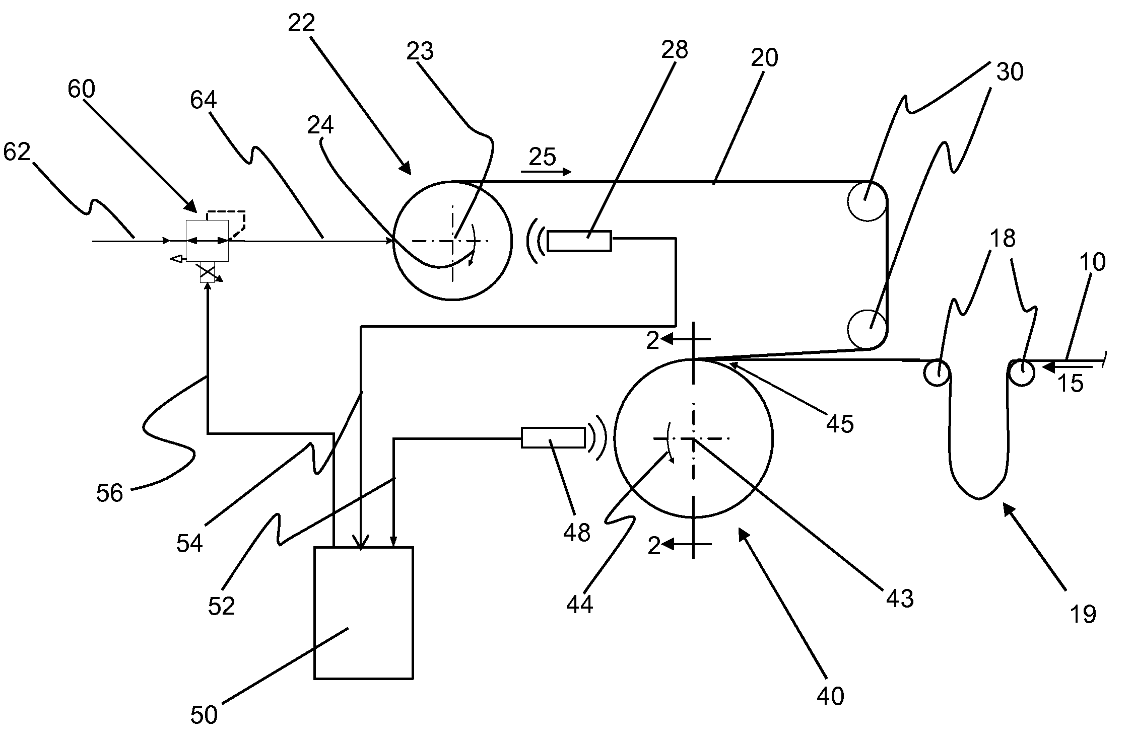
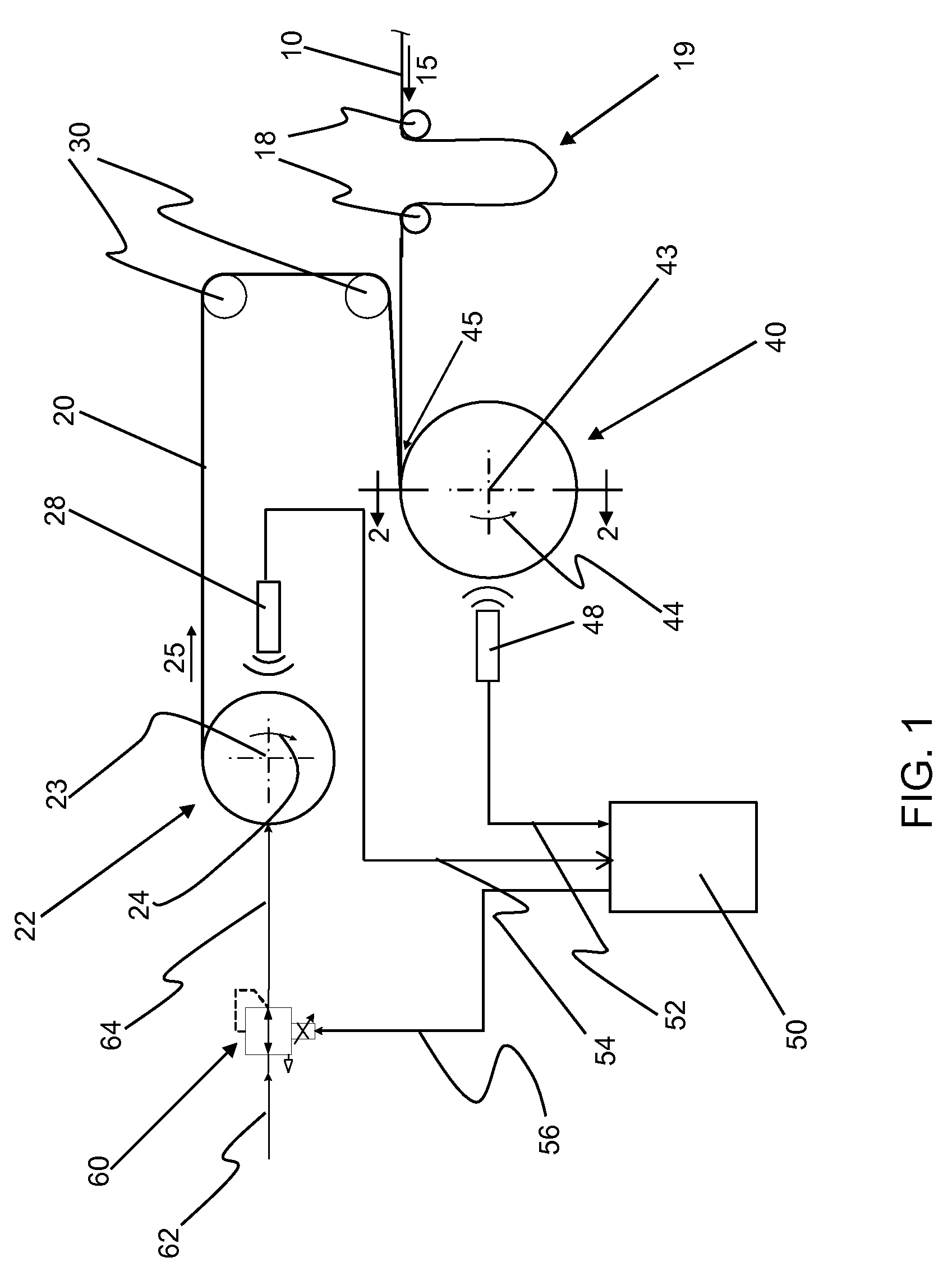
[0078]A glass ribbon having a thickness of 150 microns was wound into a roll together with an interleaving material of irradiated cross linked Ethylene Vinyl Acetate (EVA) copolymer foam having a thickness of 1 / 32 inch, a width of 11 inches (28 mm), and a density of 6 lbs. per cubic foot (0.1 grams per cubic cm) (available from FLEXcon of Spencer, Mass. as FLEXcon P.E.F. 32 white no PS). The roll was started by winding the interleaving material around a roll core (having a nominal diameter of 20 inches (508 mm), 18 inch (457 mm) minimum diameter, and 24 inch (610 mm) maximum diameter), and then feeding glass ribbon to a nip formed by the interleaving material. The parameters for winding the roll were as follows:

[0079]the roll was wound at a speed of 12.5 to 28 feet per minute (

[0080]the diameter of the finished roll (as measured to the outermost layer of the glass ribbon and interleaving material) was less than 29 inches

[0081]the breaking torque applied to the interleaving material ...

example-2

[0088]A glass ribbon and interleaving material were wound together into a roll in the same manner, and with the same equipment, as set forth in Example 1, except that the pneumatic brake was set at 5.5 in-lbs (0.62 Nm) of torque, 12 psi (0.084 MPa), for the entire rolling process, whereby it applied a tension of approximately 0.07 pounds per linear inch (0.013 kg / cm) to the interleaving at the start of rolling, which tension linearly increased to 0.5 pounds per linear inch (0.09 kg / cm) by the end of rolling. The roll of glass ribbon and interleaving material did not have straight sidewalls.

[0089]It should be emphasized that the above-described embodiments of the present invention, particularly any “preferred” embodiments, are merely possible examples of implementations, merely set forth for a clear understanding of various principles of the invention. Many variations and modifications may be made to the above-described embodiments of the invention without departing substantially fro...


PUM

PropertyMeasurementUnit
pressureaaaaaaaaaa
pressureaaaaaaaaaa
thickaaaaaaaaaa

Abstract

A method of winding a glass ribbon (10), including: winding an interleaving material (20) and the glass ribbon together to produce a roll (40); and tensioning the interleaving material so as to control a roll inter-layer pressure. By controlling the roll inter-layer pressure, the roll can be formed with straight side walls. The tension in the interleaving material can be controlled so as to be greater than 0 and ≦0.25 pounds per linear inch of width of interleaving material. Also, there is provided an apparatus for winding glass ribbon together with interleaving material into a roll. The apparatus includes: an interleaving material supply path; a glass ribbon supply path; a roll winding mechanism (46); and a means (26) for applying tension to interleaving material traveling along the interleaving material supply path, as the interleaving material is wound into roll (40), so as to produce a pressure between the layers of the roll.

Description

[0001]This application claims the benefit of priority of U.S. Provisional Application Ser. No. 61 / 417,908 filed on Nov. 30, 2010 the content of which is relied upon and incorporated herein by reference in its entirety.BACKGROUND[0002]1. Field[0003]The invention is directed to methods and apparatuses for winding glass ribbon. More particularly, the invention is directed to methods and apparatuses for winding glass ribbon together with an interleaving material to form a roll.[0004]2. Technical Background[0005]Although formed as a continuous ribbon, glass is typically segmented into sheets as soon as it has cooled and solidified. Recent product trends—in ePaper front plane substrates, protective cover sheets in photovoltaic modules, touch sensors, solid state lighting, and electronics, for example—have resulted in requirements for thinner and thinner glass. As glass thicknesses continue to decrease, however, these sheets become more flexible. This creates a challenge from a handling pe...

Claims


Application Information

Patent Timeline
Patent Type & Authority Applications(United States)
IPC IPC(8): B65H23/00
CPCB32B17/064B32B17/10B65H18/08B65H2301/414324B65H2511/142B65H23/00B65H2801/61B65H2515/34B65H2220/01B65H2220/02B32B5/18B32B17/06B32B27/32B32B29/08B32B37/10B65H2511/14B32B7/06B65H23/04C03B17/06C03B18/04
Inventor MERZ, GARY EDWARDTOSCH, JOHN EARLTRZECIAK, THADDEUS FRANCIS
Owner CORNING INC
Why Eureka
Try Eureka