Component having a micromechanical microphone structure

a micro-mechanical and microphone technology, applied in the field of micro-mechanical microphone structures, can solve the problems of increasing thermal noise pressure on the diaphragm, reducing the sensitivity of the microphone to low-frequency acoustic signals, etc., and achieves the performance of the microphone component according to the present invention, and improving the acoustic seal

Inactive Publication Date: 2013-09-19
ROBERT BOSCH GMBH
View PDF2 Cites 23 Cited by
  • Summary
  • Abstract
  • Description
  • Claims
  • Application Information

AI Technical Summary

Benefits of technology

[0019]At this point it is expressly pointed out that the diaphragm of a microphone component according to the present invention may also be equipped with multiple structural element formations which surround the sound opening. Thus, for example, two closed circumferential walls may be provided which are situated concentrically with respect to one another on the same diaphragm surface, or which also protrude from the front side and the back side of the diaphragm. Another option is to combine multiple perforated circumferential walls which are concentrically situated with respect to one another in such a way that the gaps in one circumferential wall are in each case positioned with an offset relative to the gaps in the adjacent wall(s). In this case as well, the individual wall sections of the circumferential walls may be provided either on the same diaphragm surface or on the front side and the back side of the diaphragm. Lastly, it is noted that one or multiple closed circumferential wall(s) may be combined with one or m

Problems solved by technology

However, the sensitivity of the microphone to low-frequency acoustic signals is als

Method used


Image

  • Component having a micromechanical microphone structure
  • Component having a micromechanical microphone structure
  • Component having a micromechanical microphone structure

Examples


Embodiment Construction

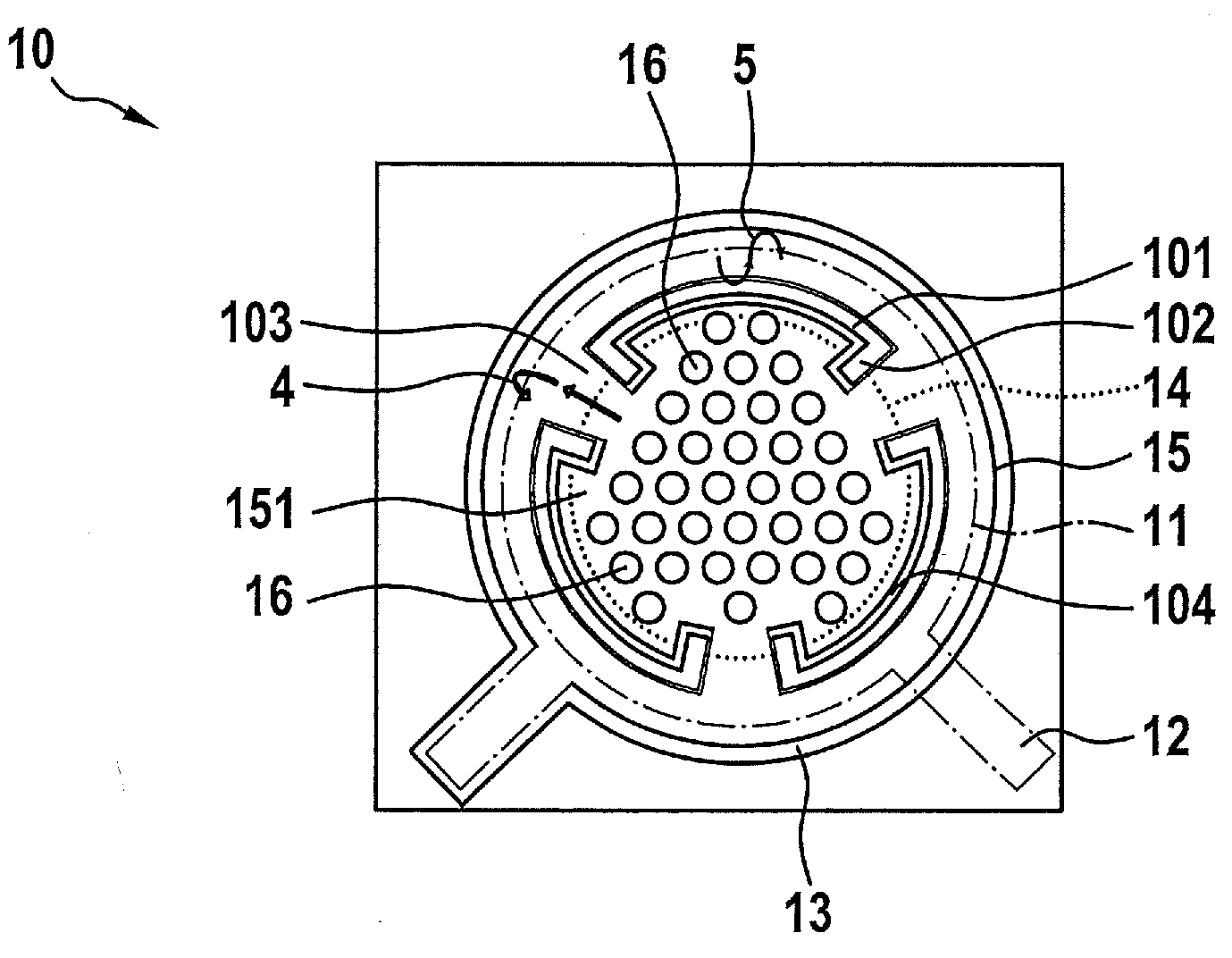
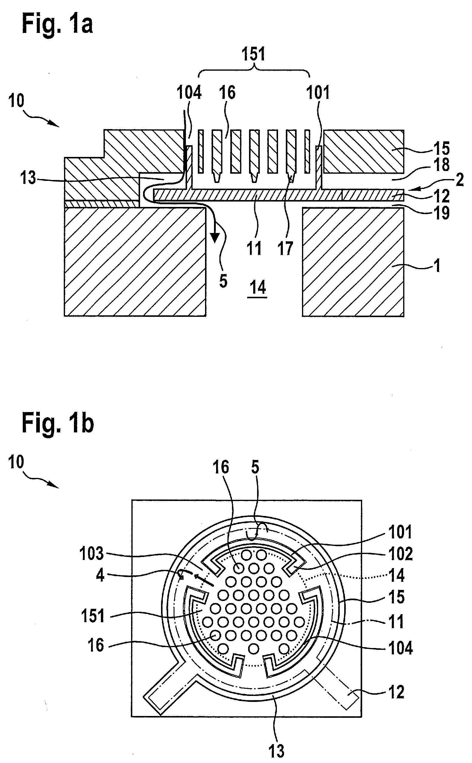
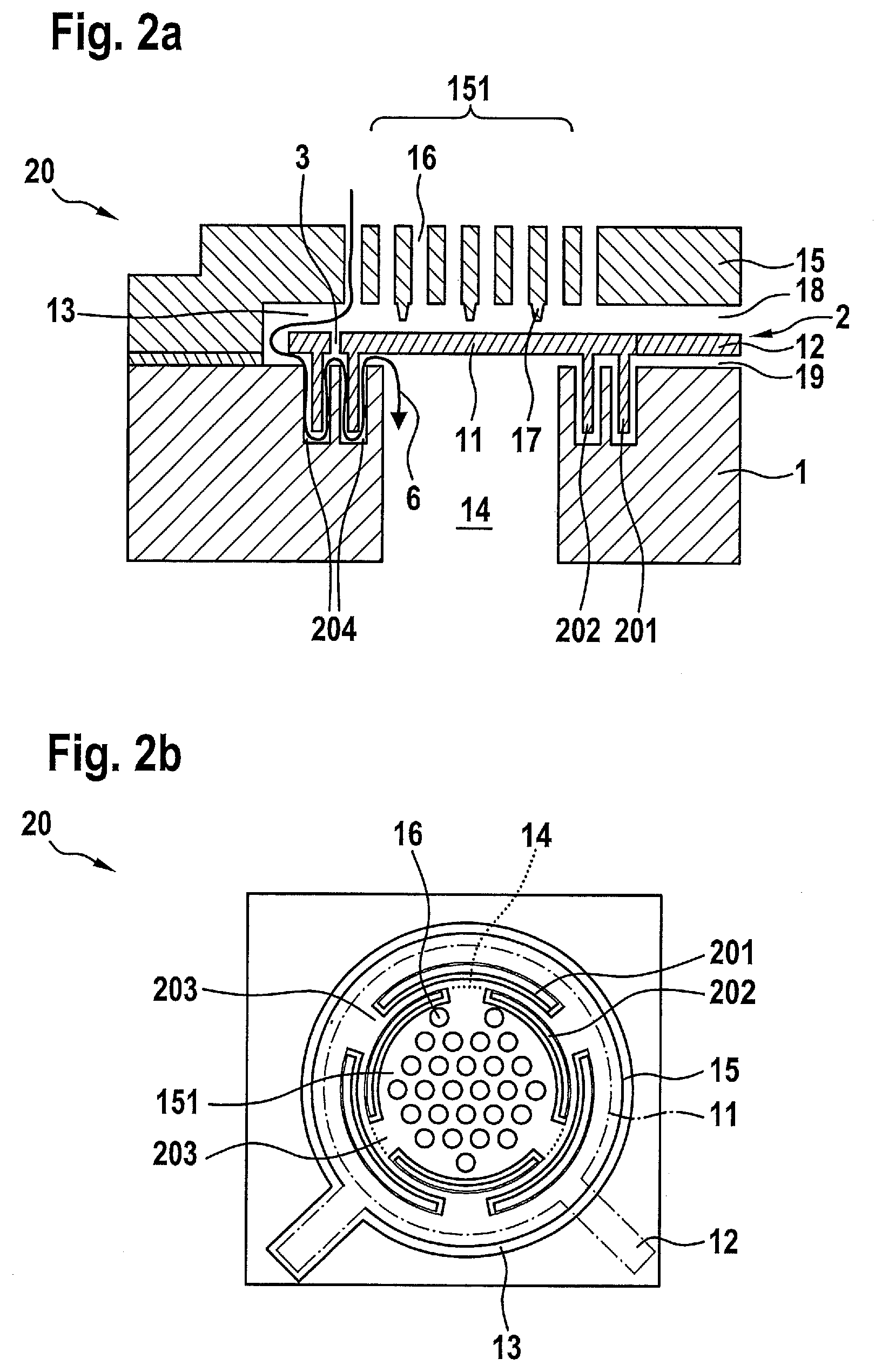
[0027]Since the microphone structures of the three MEMS microphone components 10, 20, and 30 illustrated in the figures differ essentially only in the characteristics of the ridge-like structural elements 101, 201 and 202, and 301 and 302, respectively, the common features of these three microphone components 10, 20, and 30 are initially discussed in the following. Identical reference numerals are used for identical components.

[0028]In all three exemplary embodiments, the microphone structure is implemented in a layered structure on a semiconductor substrate 1. The microphone structure includes a diaphragm structure 2 which is provided in a relatively thin diaphragm layer above semiconductor substrate 1. This diaphragm layer may be composed of one or also multiple material layers. In this case, diaphragm structure 2 essentially includes a circular acoustically active diaphragm 11 and at least one spring element 12 via which diaphragm 11 is integrated into the layered structure of co...


PUM


Abstract

A micromechanical microphone structure configured as a layered structure includes: a semiconductor substrate; a diaphragm structure having an acoustically active diaphragm which at least partially spans a sound opening in the back side of the substrate and is provided with a movable electrode of a microphone capacitor, which diaphragm structure has openings via which pressure compensation occurs between the back side and the front side of the diaphragm; a stationary acoustically permeable counterelement having vents, which counterelement is situated in the layered structure above the diaphragm and which functions as a carrier for a nonmovable electrode of the microphone capacitor; and at least one ridge-like structural element which is situated at the outer edge area of the diaphragm, and which protrudes from the diaphragm plane into corresponding recesses in an adjoining layer.

Description

BACKGROUND OF THE INVENTION[0001]1. Field of the Invention[0002]The present invention relates to a component having a micromechanical microphone structure which is implemented in a layered structure on a semiconductor substrate. The microphone structure includes a diaphragm structure having an acoustically active diaphragm which at least partially spans a sound opening in the back side of the substrate. The diaphragm is provided with a movable electrode of a microphone capacitor. In addition, openings are provided in the diaphragm structure, via which pressure compensation occurs between the back side and the front side of the diaphragm. Moreover, the microphone structure includes a stationary acoustically permeable counterelement having vents, which is situated in the layered structure above the diaphragm and which functions as a carrier for a nonmovable electrode of the microphone capacitor.[0003]2. Description of the Related Art[0004]The diaphragm of the type described above is a...

Claims


Application Information

Patent Timeline
IPC IPC(8): H04R1/08
CPCH04R19/005H04R1/08H04R19/04
Inventor ZOELLIN, JOCHENSCHELLING, CHRISTOPH
Owner ROBERT BOSCH GMBH
Why Eureka
Try Eureka