Serviceable soffit vent

a ventilator and soffit technology, applied in ventilation systems, lighting and heating apparatus, heating types, etc., can solve the problems of affecting the appearance of the attic, promoting mold and decay in the attic, and affecting the ventilation of the attic, so as to protect the structural integrity and aesthetic integrity

a ventilator and soffit technology, applied in ventilation systems, lighting and heating apparatus, heating types, etc., can solve the problems of affecting the appearance of the attic, promoting mold and decay in the attic, and affecting the ventilation of the attic, so as to protect the structural integrity and aesthetic integrity

US20130247480A1Inactive Publication Date: 2013-09-26RIDGWAY MICHAEL DUANE

Image

  • Serviceable soffit vent
  • Serviceable soffit vent
  • Serviceable soffit vent

Examples


Embodiment Construction

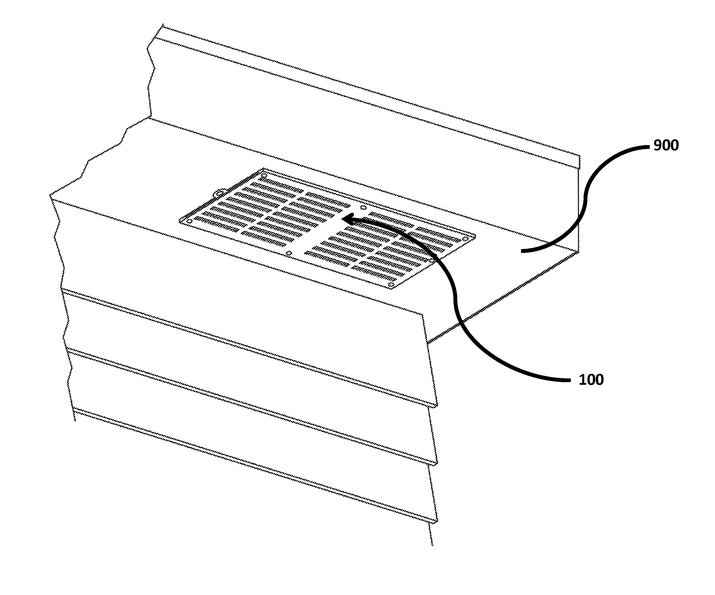
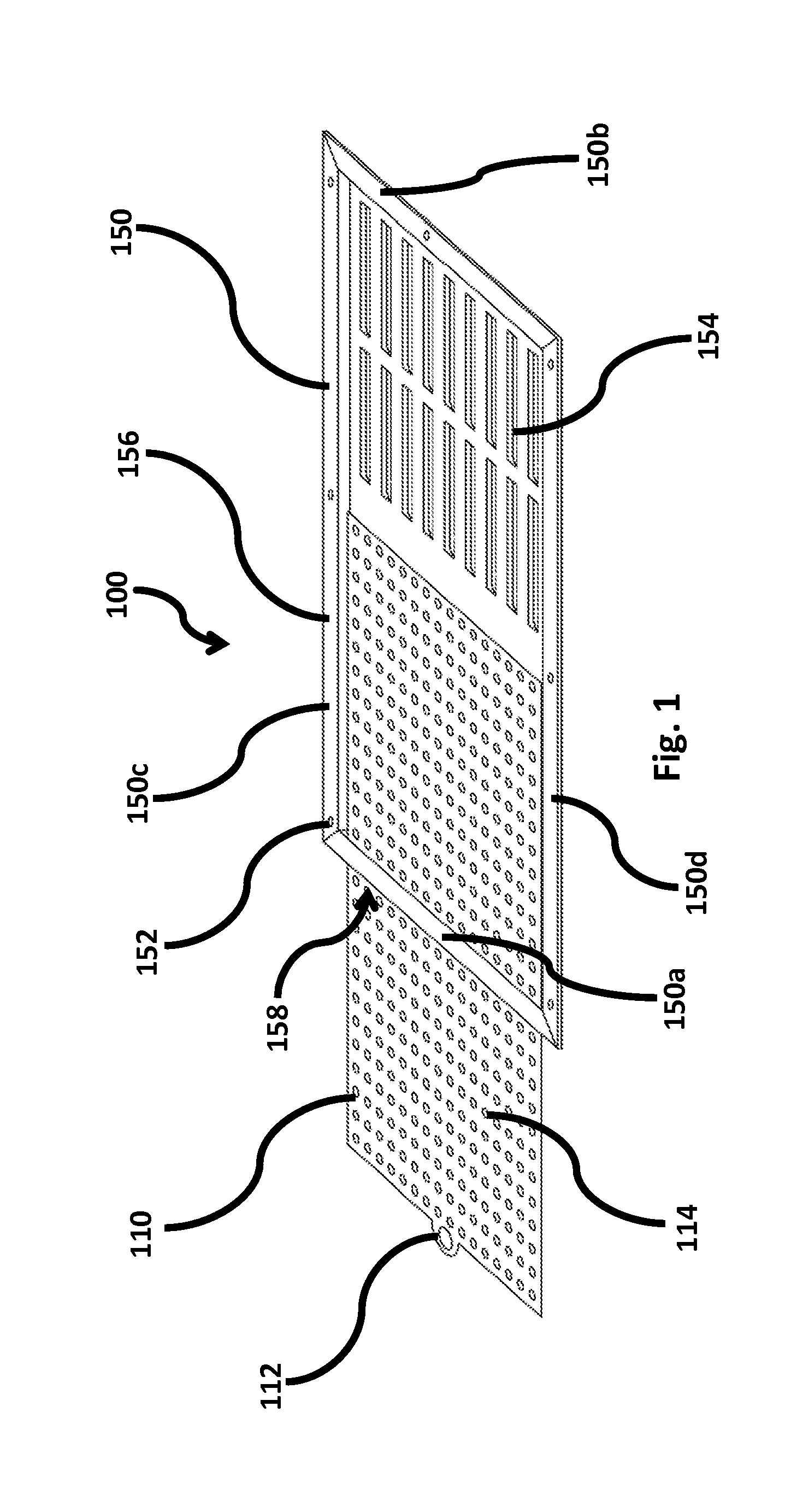
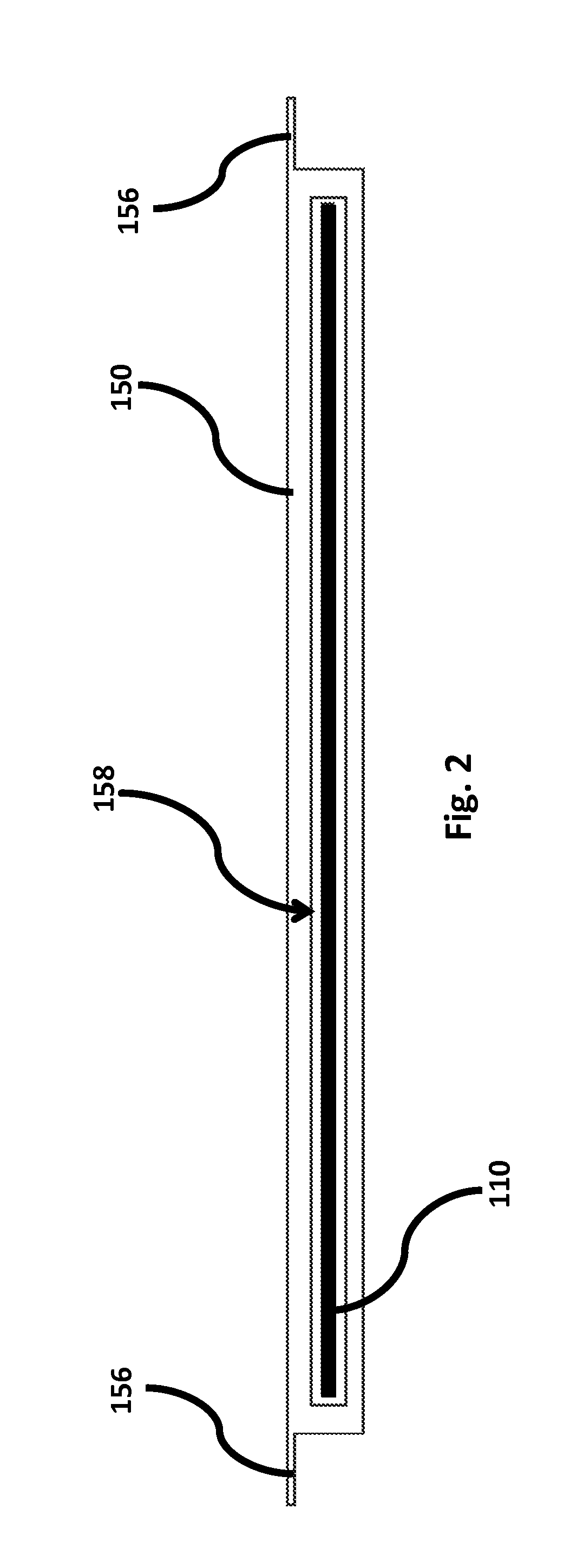
[0019]FIGS. 1-2 illustrate one embodiment of the serviceable soffit vent assembly 100. Here, vent 100 includes a frame 150 having a first end 150a and a second end 150b, top end 150c and bottom end 150d. In the current embodiment, frame 150 has a rectangular configuration, however, it contemplated within the scope of the invention that frame 150 can be any size, dimension, or shape, including but not limited to a square, circle, cylindrical, oval, ellipsoid, triangular, asymmetrical, or any polygon having three or more sides. Further, frame 150 includes a plurality of fixed louvered openings 154. In the current embodiment, there are five columns of louvers, wherein each column has 13, thereby the vent having a total of 65 louvered air openings. However, it is contemplated within the scope of the invention that there can be any number of louvers, louvers columns, air intake openings, or any arrangement or configuration of louvers or air intake openings. In addition, ends 150a-150d of...


PUM


Abstract

An attic soffit ventilator for a dwelling having a removable filter. The soffit ventilator includes a frame having a plurality of louvers on one side, wherein the frame is fixed to the underside surface or soffit structure of a roof. The frame includes a side openings or slot for receiving a filter media. The filter media is inserted into the frame by sliding it into the frame from the side opening or slot. Further, the filter media can be removed, cleaned, and re-inserted into the frame.

Description

CROSS REFERENCE TO RELATED APPLICATIONS[0001]This application is a continuation-in-part of and claims the benefit of U.S. Non-Provisional Application Ser. No. 13 / 199,288 filed on Aug. 24, 2011.FIELD OF THE INVENTION[0002]The present invention is a system and device for ventilating the attic of a dwelling. More specifically, a serviceable soffit ventilator is provided having a removable and re-usable filter.BACKGROUND[0003]Excessive heat and moisture trapped in an attic or other space underneath the pitched roof of a structure can damage the roof, can damage the remainder of the structure and can promote mold and decay within the attic. To avoid these effects, the ambient air space between the roof and dwelling ceiling, referred to as the attic, must be constantly ventilated, and replaced with fresh contiguous outside ambient air.[0004]During daylight hours, the sun shining on the roof warms the deck surface, causing the deck to become warmer than the ambient air. The warm roof deck ...

Claims


Application Information

Patent Timeline
26 Sep 2013
Publication
US20130247480A1
IPC
E04D13/17
CPC
E04D13/152; E04D13/178
Inventors
RIDGWAY, MICHAEL DUANE