Induction heating device, induction heating method, and program

a technology of induction heating and inverter, which is applied in the direction of induction heating, electric/magnetic/electromagnetic heating, induction current sources, etc., can solve the problems of increasing the power loss of the switching element during the turn-on, and achieve the effect of reducing the surge voltage and reducing the switching loss of the inverter

Active Publication Date: 2013-09-26
MITSUI E&S MACHINERY CO LTD
View PDF5 Cites 18 Cited by
  • Summary
  • Abstract
  • Description
  • Claims
  • Application Information

AI Technical Summary

Benefits of technology

[0017]According to the present invention, the switching loss of the inverter is reduced regardless of the pulse width. Surge voltage during switching is also reduced.

Problems solved by technology

It describes that a resonance type converter circuit in a resonant current phase lead mode is turned on in the zero-current switching, and that a reverse recovery current of a commutation diode is added to the resonant current as a current flowing through the switching element, due to the reverse recovery operation of the commutation diode at turn-on of the switching element, which results in the increase in turn-on power loss of the switching element.

Method used


Image

  • Induction heating device, induction heating method, and program
  • Induction heating device, induction heating method, and program
  • Induction heating device, induction heating method, and program

Examples


first embodiment

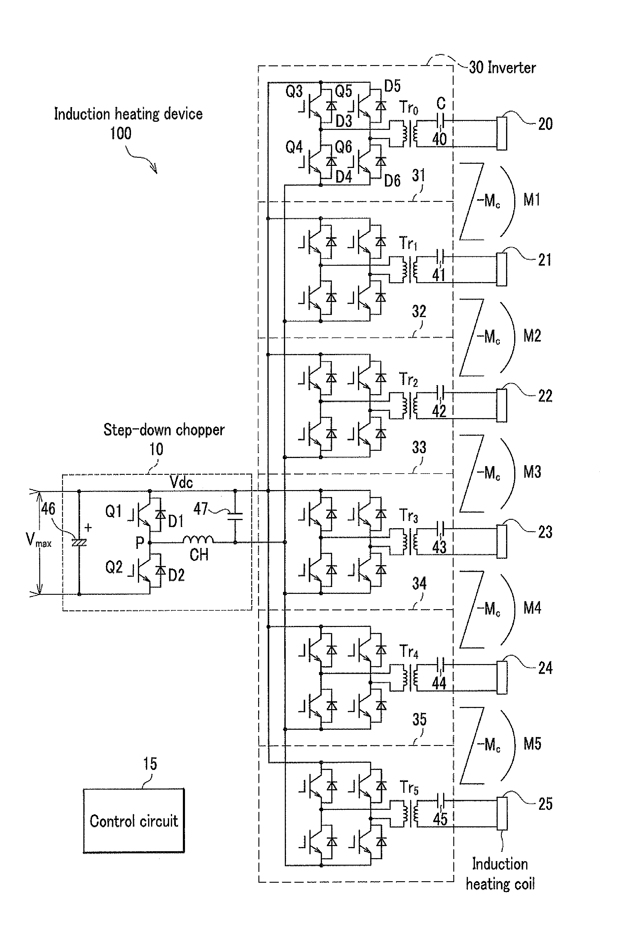
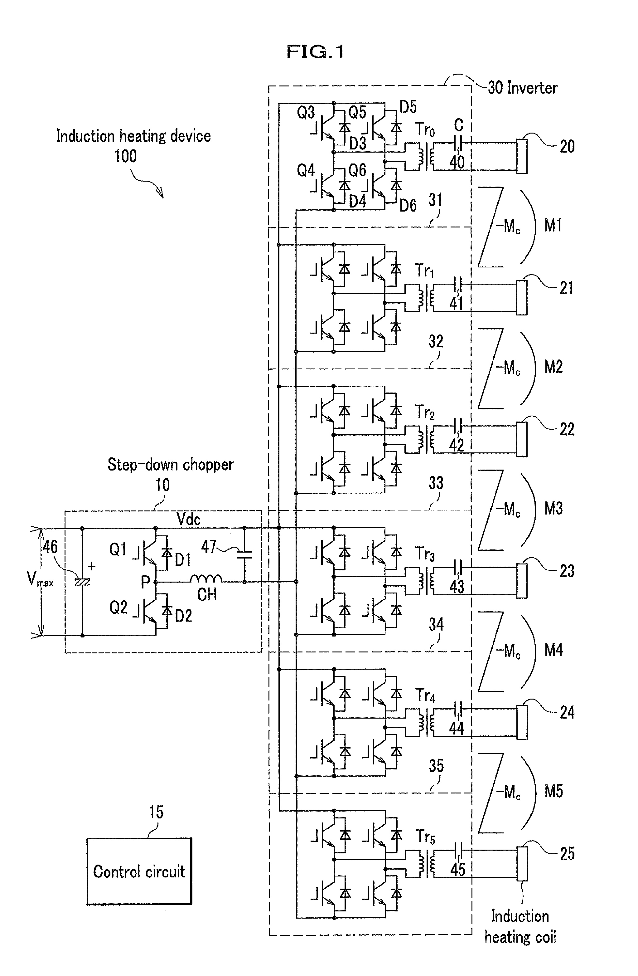
[0028]The configuration of an induction heating device of the present invention will be described with reference to FIG. 1 and FIG. 2.

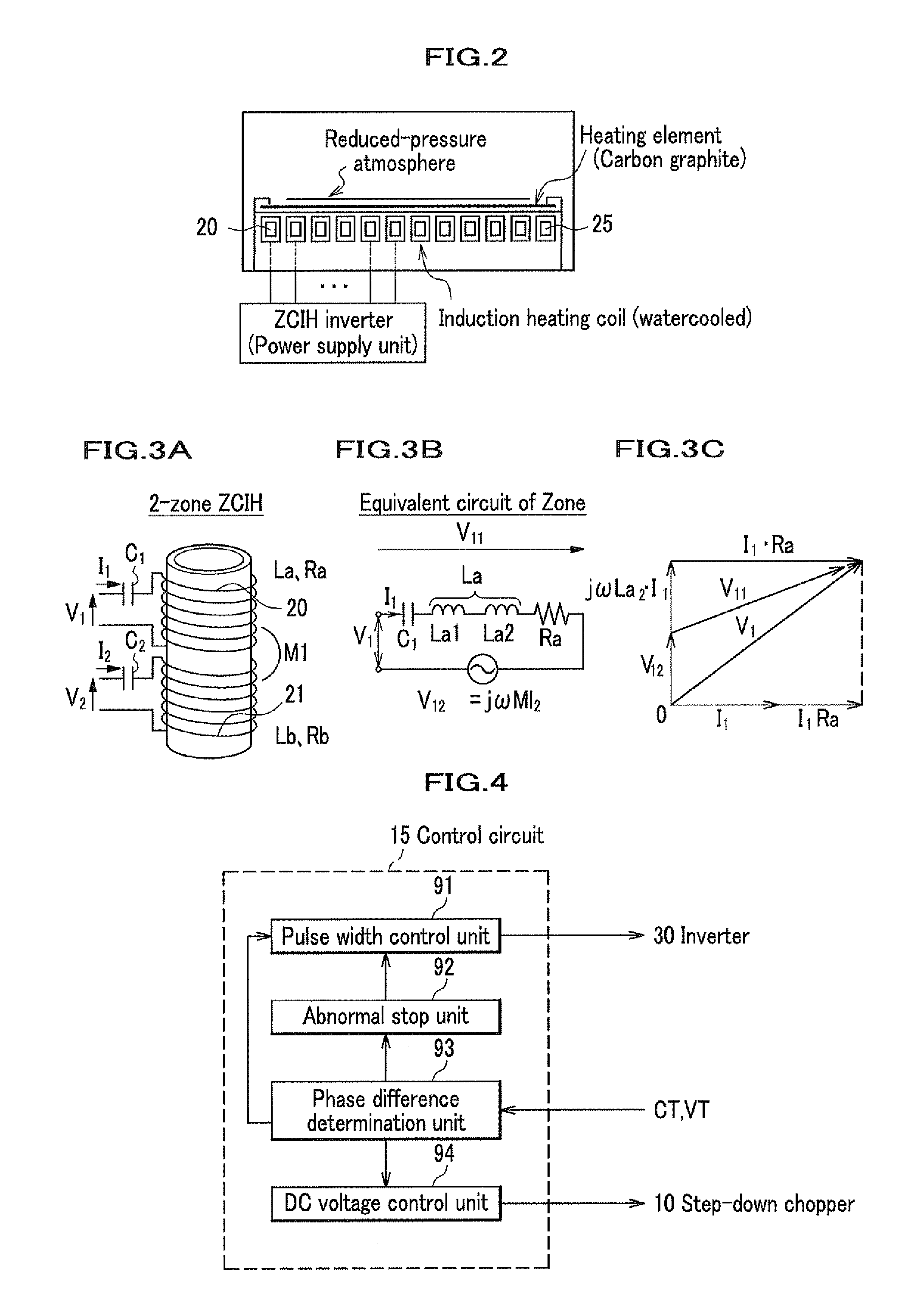
[0029]In FIG. 1, the induction heating device 100 includes a step-down chopper 10, a plurality of inverters 30, 31, . . . , 35, a plurality of induction heating coils 20, 21, . . . , 25, and a control circuit 15, wherein each of the induction heating coils 20, 21, . . . , 25 flows an eddy current in a common heating element (e.g., carbon graphite) (FIG. 2) by generating a high-frequency magnetic flux, thereby heating the heating element.

[0030]In addition, the induction heating device 100 is controlled to synchronize current phases and the frequencies of all induction heating coils 20, 21, . . . , 25, in order to reduce the influence of the mutually induced voltage by induction heating coils adjacent to each other. As the current phases of induction heating coils 20, 21, . . . , 25 are controlled to be aligned and there is no phase difference in genera...


PUM


Abstract

The purpose of the present invention is to minimize switching losses of an inverter. An induction heating device includes: a plurality of induction heating coils (20) which are disposed adjacent with each other; a plurality of inverters (30), each of which has a capacitor (40) serially connected to each of the induction heating coils (20), and converts a DC voltage into a square wave voltage; and a control circuit (15) which controls so as to align the phase of coil currents flowing though the plurality of the induction heating coils (20), wherein the control circuit (15) controls the timing at which the square wave voltage transitions such that an instantaneous value of the square wave voltage is preserved in either the DC voltage or a turnover voltage, when the coil current zero crosses.

Description

CROSS REFERENCE TO RELATED APPLICATION[0001]The present application claims benefit of the filing date of PCT Application No. PCT / JP2010 / 071690 filed on Dec. 3, 2010 which is incorporated herein by reference.TECHNICAL FIELD[0002]The present invention relates to an induction heating device, an induction heating method, and a program, using a plurality of induction heating coils.BACKGROUND OF THE INVENTION[0003]It is necessary for a semiconductor manufacturing apparatus for heat-treating wafers to control the temperature difference on the surface of the wafer as small as possible (e.g., within a range of plus or minus one degree Celsius) to avoid thermal strain and others. In addition, it is necessary to elevate the temperature fast (e.g., 100° C. / s) to the desired temperature (e.g., 1350° C.). Accordingly, an induction heating device is widely known in which an induction heating coil is divided into a plurality thereof and a power control is performed by connecting a high-frequency po...

Claims


Application Information

Patent Timeline
Patent Type & Authority Applications(United States)
IPC IPC(8): H05B6/08H05B6/44
CPCH05B6/06H05B6/44H05B6/08H05B6/04H05B6/062
Inventor UCHIDA, NAOKIOKAZAKI, YOSHIHIROOZAKI, KAZUHIRO
Owner MITSUI E&S MACHINERY CO LTD
Why Eureka
Try Eureka