
Passive phase change radiators for LED lamps and fixtures

a technology of led lamps and radiators, applied in the field of lamps or lighting fixtures, can solve the problems of incandescent lights being very energy-inefficient light sources, inability to generate white light from active layers, and still relatively inefficien

Active Publication Date: 2013-09-26
IDEAL IND LIGHTING LLC
View PDF14 Cites 33 Cited by
  • Summary
  • Abstract
  • Description
  • Claims
  • Application Information

AI Technical Summary

Benefits of technology

The present invention is about heat radiators that can be used in lamps or light fixtures with LEDs. These heat radiators have a coolant loop that carries a fluid that absorbs the heat from the LEDs and releases it into the surrounding air. The coolant loop is in thermal contact with the LEDs, allowing for efficient heat transfer. This invention helps to manage the heat generated by LEDs, which can improve the performance and lifespan of LED-based lamps or light fixtures.

Problems solved by technology

However, conventional LEDs cannot generate white light from their active layers.
Incandescent lights are very energy-inefficient light sources with approximately ninety percent of the electricity they consume being released as heat rather than light.
Fluorescent light bulbs are more energy efficient than incandescent light bulbs by a factor of about 10, but are still relatively inefficient.
In addition, LEDs can have a significantly longer operational lifetime.
Incandescent light bulbs have relatively short lifetimes, with some having a lifetime in the range of about 750-1000 hours.
Fluorescent bulbs can also have lifetimes longer than incandescent bulbs such as in the range of approximately 10,000-20,000 hours, but provide less desirable color reproduction.
Operating at elevated temperatures can cause damage to the LEDs and / or their surrounding features, which can reduce their lifespan and reliability.
These types of heat sinks can be relatively large and bulky, and can result in a lamp that exceeds the desired geometric form factor for the lamp (e.g. standard A19 form factor).
In addition, despite their large sizes, many passive heat sinks may not comply with the thermal requirement of the LED lamp or fixture.
This can result in an overall increase in power consumption for the lamp as well as potential failure of the moving parts.

Method used


Image

  • Passive phase change radiators for LED lamps and fixtures
  • Passive phase change radiators for LED lamps and fixtures
  • Passive phase change radiators for LED lamps and fixtures

Examples


Embodiment Construction

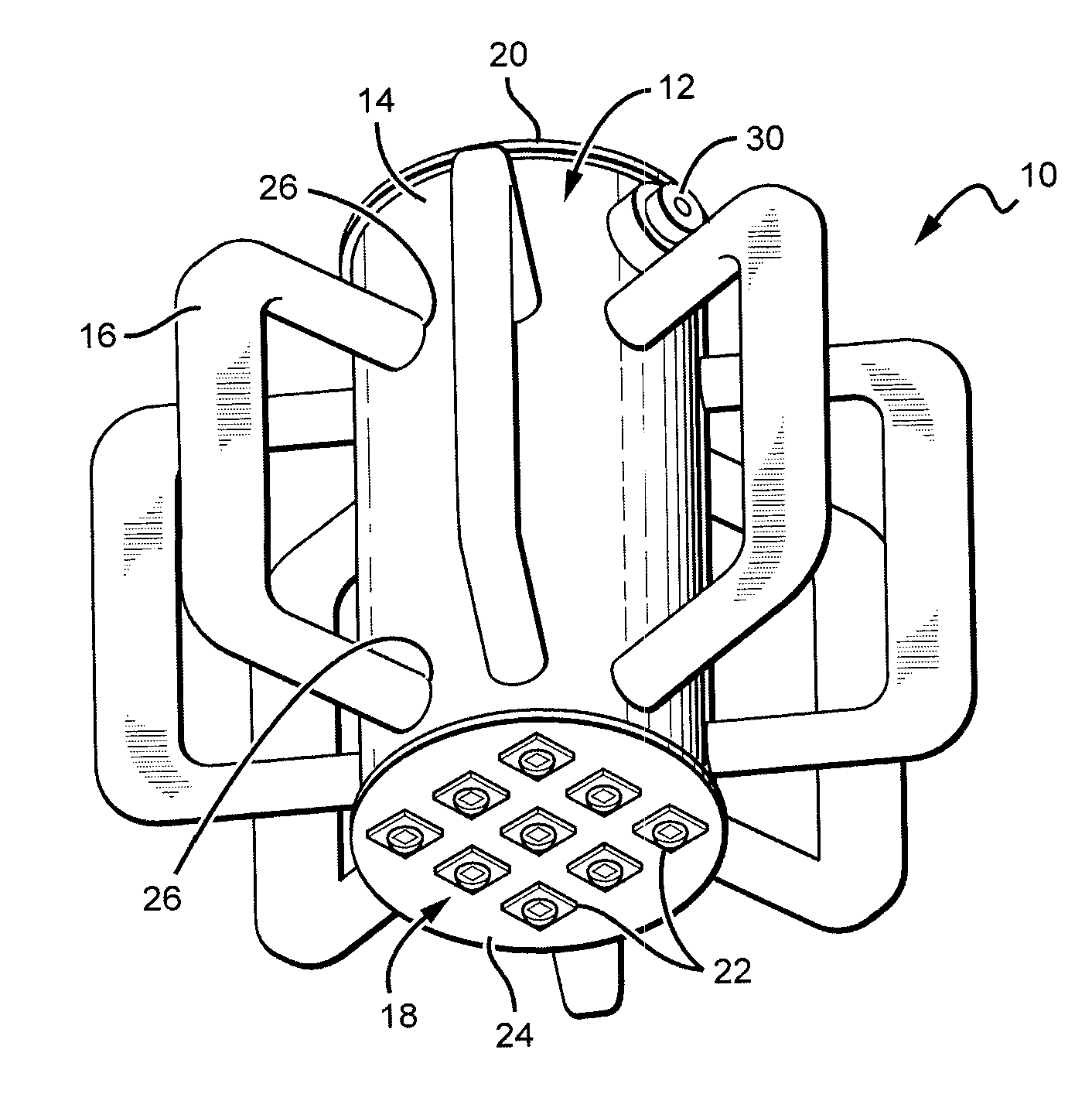
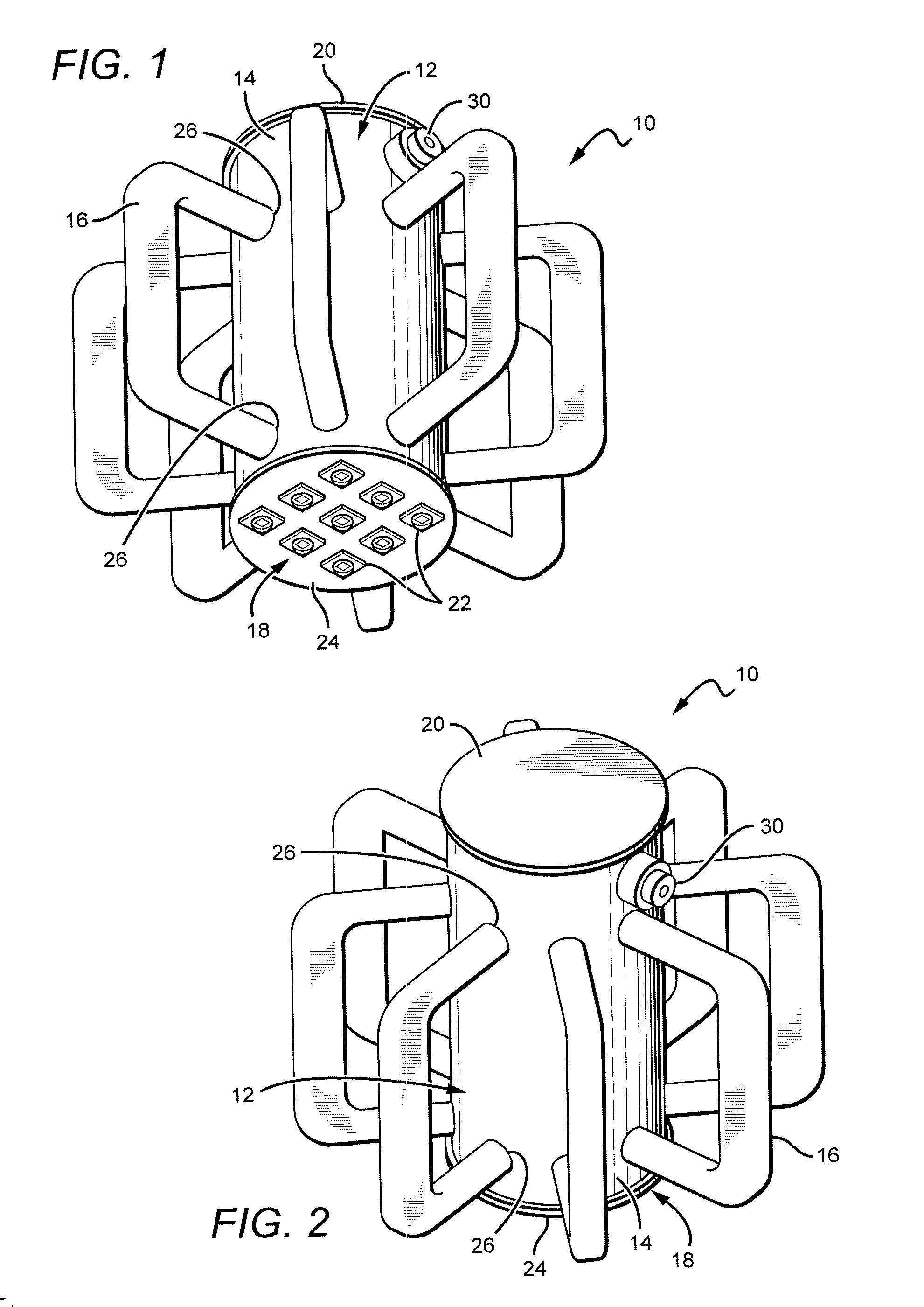
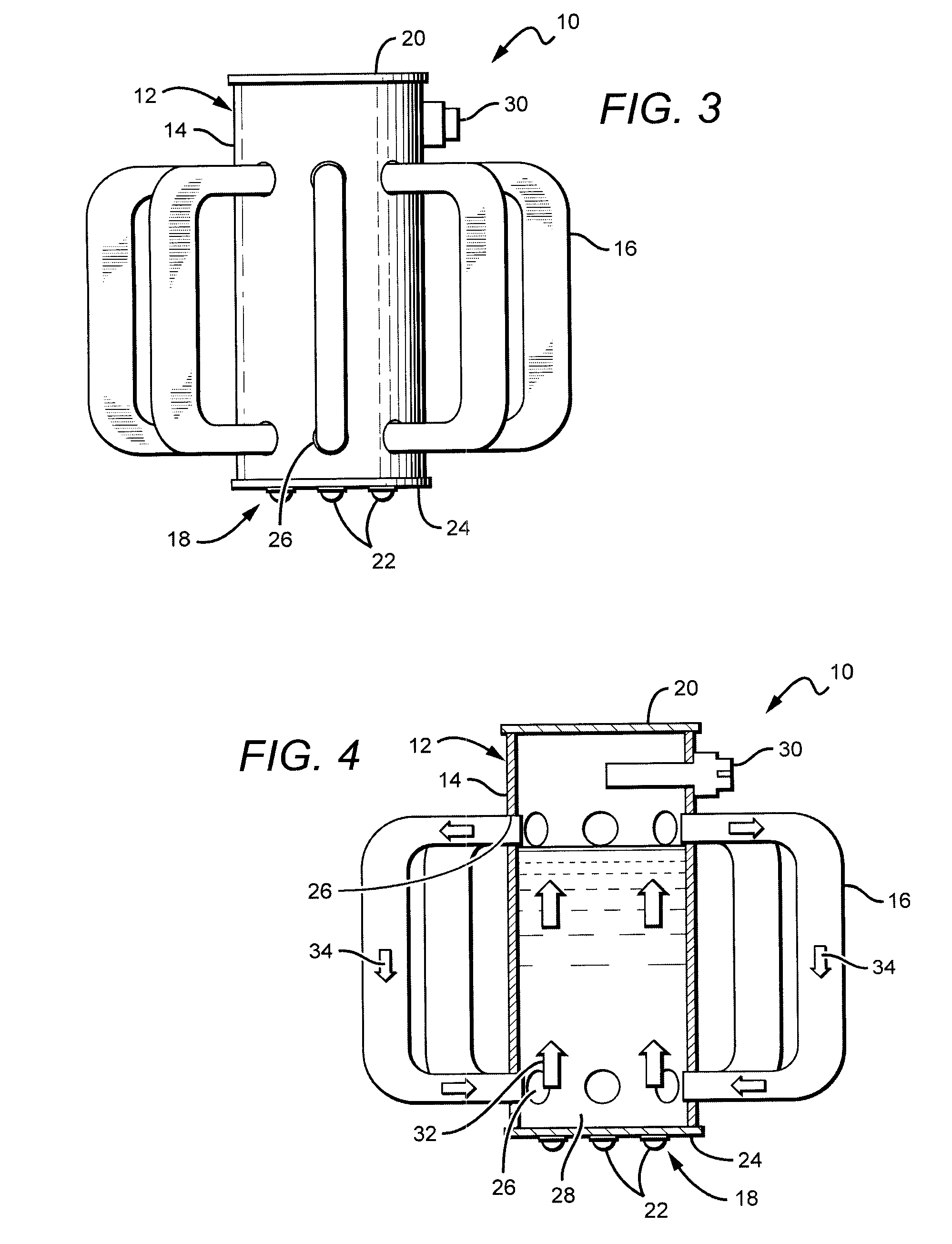
[0026]The present invention provides heat management devices and structures that can be used in lamps and fixtures (“lamps”) having solid state light sources, such as one or more LEDs. Some lamp embodiments according to the present invention comprise one or more phase change radiators that utilize the latent heat of fluids to circulate and draw heat away from the LEDs and radiate the heat into the ambient, allowing for the LEDs to operate at a lower temperature. Latent heat is the heat energy required to change a fluid's liquid state to a gas state, and during this phase change state, the temperature does not change. Some phase change radiators according to the present invention can comprise a main radiator body and multiple radiator coolant loops mounted to the body. The present invention relies on the circulation of the “hot” fluid and gas utilizing the pressure differential between the two states. The process converts the LED heat loss energy to the fluid latent heat energy and f...


PUM


Abstract

Heat management devices and structures are disclosed that can be used in lamps having solid state light sources such as one or more LEDs. Some lamp embodiments comprise one or more phase change radiators that utilize the latent heat of fluids to circulate and draw heat away from the LEDs and radiate the heat into the ambient, allowing for the LEDs to operate at a lower temperature. Some phase change radiators according to the present invention can comprise a main radiator body and multiple radiator coolant loops mounted to the body. The present invention relies on the circulation of heated fluid through the radiator body to radiate heat from the LEDs. The heated liquid moves away from the LEDs and is circulated back to thermal contact with the LEDs thought the coolant loops.

Description

BACKGROUND OF THE INVENTION[0001]1. Field of the Invention[0002]The present invention relates generally to lamps or lighting fixtures, and more particularly to lamps and fixtures utilizing light emitting diodes (LEDs) and phase change heat radiators.[0003]2. Description of the Related Art[0004]Light emitting diodes (LED or LEDs) are solid state devices that convert electric energy to light and generally comprise an active region of semiconductor material sandwiched between two oppositely doped layers of semiconductor material. When a bias is applied across the doped layers, holes and electrons are injected into the active region where they recombine to generate light. Light is emitted from the active layer and from all surfaces of the LED.[0005]LEDs can be fabricated to emit light in various colors. However, conventional LEDs cannot generate white light from their active layers. Light from a blue emitting LED has been converted to white light by surrounding the LED with a yellow pho...

Claims


Application Information

Patent Timeline
Patent Type & Authority Applications(United States)
IPC IPC(8): F21V29/00
CPCF21V29/006F21V3/00F21Y2101/02F21Y2115/10F21V29/00F21V29/59F21V29/717
Inventor LE, LONG LARRYPROGL, CURTIS L.LAY, JAMES MICHAELBLACKWELL, RONALDJAMES, SR., MALCOLM D.PONCHERI, MICHAEL D.TAYLOR, JASON
Owner IDEAL IND LIGHTING LLC
Learn More