
Liquid drop ejecting head, image forming device, and method of manufacturing liquid drop ejecting head

a technology of liquid drop ejection and image forming device, which is applied in the direction of printing, etc., can solve the problems of difficult to form uniform plasma polymerized film, and difficult to adhere to the surface parallel to the surface facing the electrode, etc., to achieve excellent liquid resistance

Inactive Publication Date: 2013-09-26
RICOH KK
View PDF5 Cites 2 Cited by
  • Summary
  • Abstract
  • Description
  • Claims
  • Application Information

AI Technical Summary

Benefits of technology

The present patent is about a liquid drop ejecting head which has a protection film on the inside walls of its liquid chamber. This film is uniform in thickness and has excellent resistance to liquids, without affecting the underlying chamber. The technical effect of this invention is the increased durability and reliability of the liquid ejection head.

Problems solved by technology

Especially, when an alkaline ink is used and a liquid chamber substrate to form an ink jet printing head is made of a silicon material, there is a problem that inner side walls of a liquid chamber formed in the liquid chamber substrate are easily eroded by the alkaline ink.
It has been difficult to form a uniform plasma polymerized film having a predetermined thickness on the inner side walls of the liquid chamber.
For this reason, in the liquid chamber formed by etching the liquid chamber substrate, the plasma polymerized film is uniformly formed on the surfaces facing the electrodes, but the ionized components of the plasma polymerized film cannot easily be caused to adhere to the surfaces parallel to the surfaces facing the electrodes.
As a result, the thickness distribution of the plasma polymerized film formed is not uniform, and a thin portion in the thickness distribution which is less than a predetermined thickness is vulnerable to erosion.
The liquid resistance of such a thin portion becomes excessively low.
In this thermal oxidation method, an oxide film is deposited at high temperature, and there has been a problem that the liquid chamber substrate which forms the liquid chamber is deformed by the heating.

Method used


Image

  • Liquid drop ejecting head, image forming device, and method of manufacturing liquid drop ejecting head
  • Liquid drop ejecting head, image forming device, and method of manufacturing liquid drop ejecting head
  • Liquid drop ejecting head, image forming device, and method of manufacturing liquid drop ejecting head

Examples


example 1

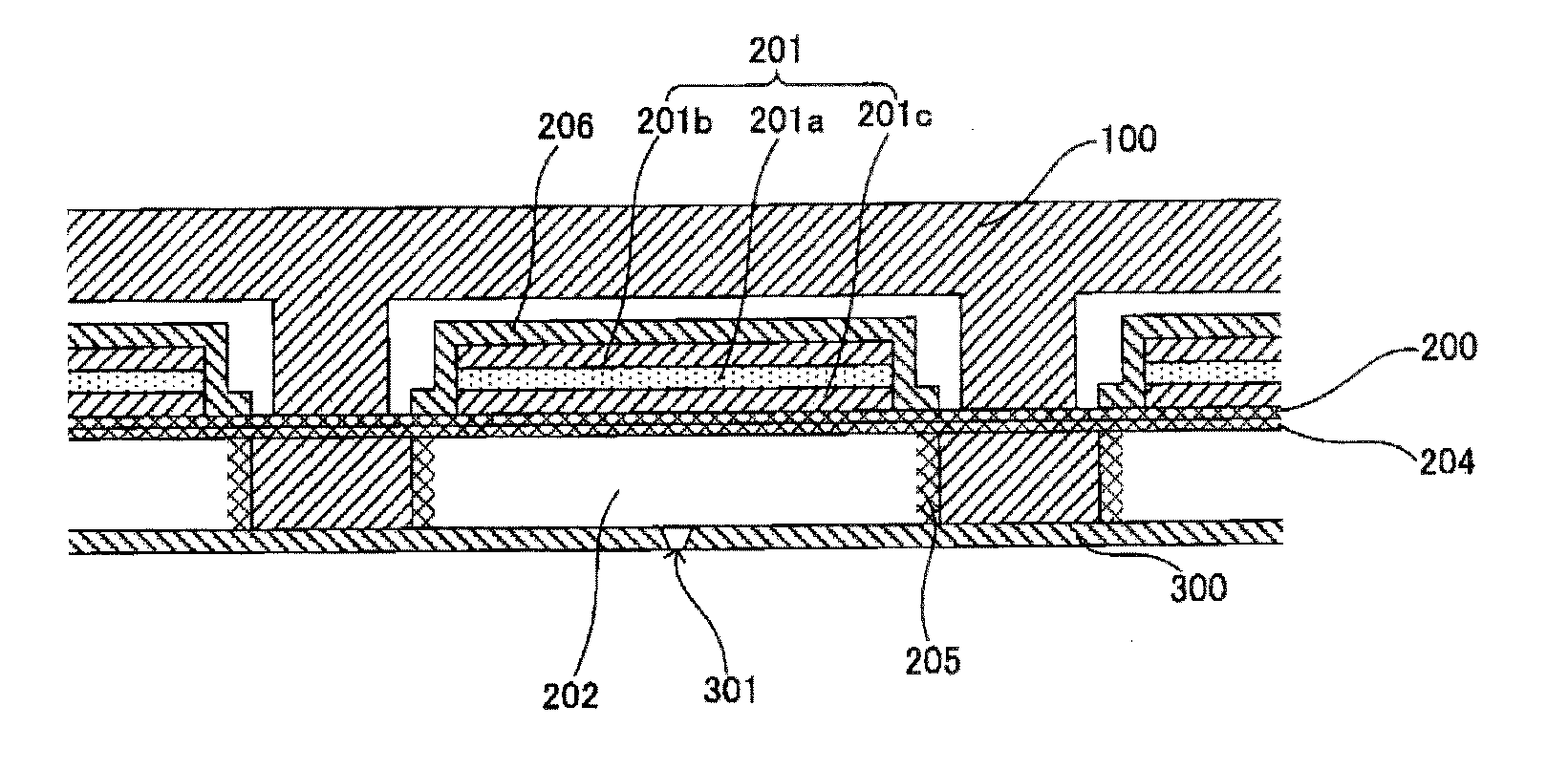
[0066]In a liquid drop ejecting head of this example, liquid chambers are formed in a liquid chamber substrate which is a silicon substrate, and a protection film is formed on an inner side wall of each liquid chamber by a chemical reaction of fluorocarbon and silicon fluoride oxide of a by-product formed on the inner side wall of each liquid chamber with the formation of the liquid chambers in the liquid chamber substrate. According to this example, as in the above-described embodiment, with the etching gas supplied into the enclosed space where the actuator plate 200 is arranged, dry etching of the actuator plate 200 is performed, and a part of each liquid chamber is formed. On the inner side wall of each liquid chamber being formed by the dry etching, a film 401 of silicon fluoride oxide of a by-product is formed by a chemical reaction of sulfur hexafluoride of the etching gas and silicon of the actuator plate 200. It has been confirmed that this film 401 is formed with a uniform...

example 2

[0067]In the liquid drop ejecting head of Example 1, a transition metal oxide film is formed on the protection film. According to this example, as in the above-described modification, with the two-layer laminated structure of the metal oxide film 501 and the liquid contact film 402, the liquid resistance is improved and good reliability over an extended period of time is provided.

example 3

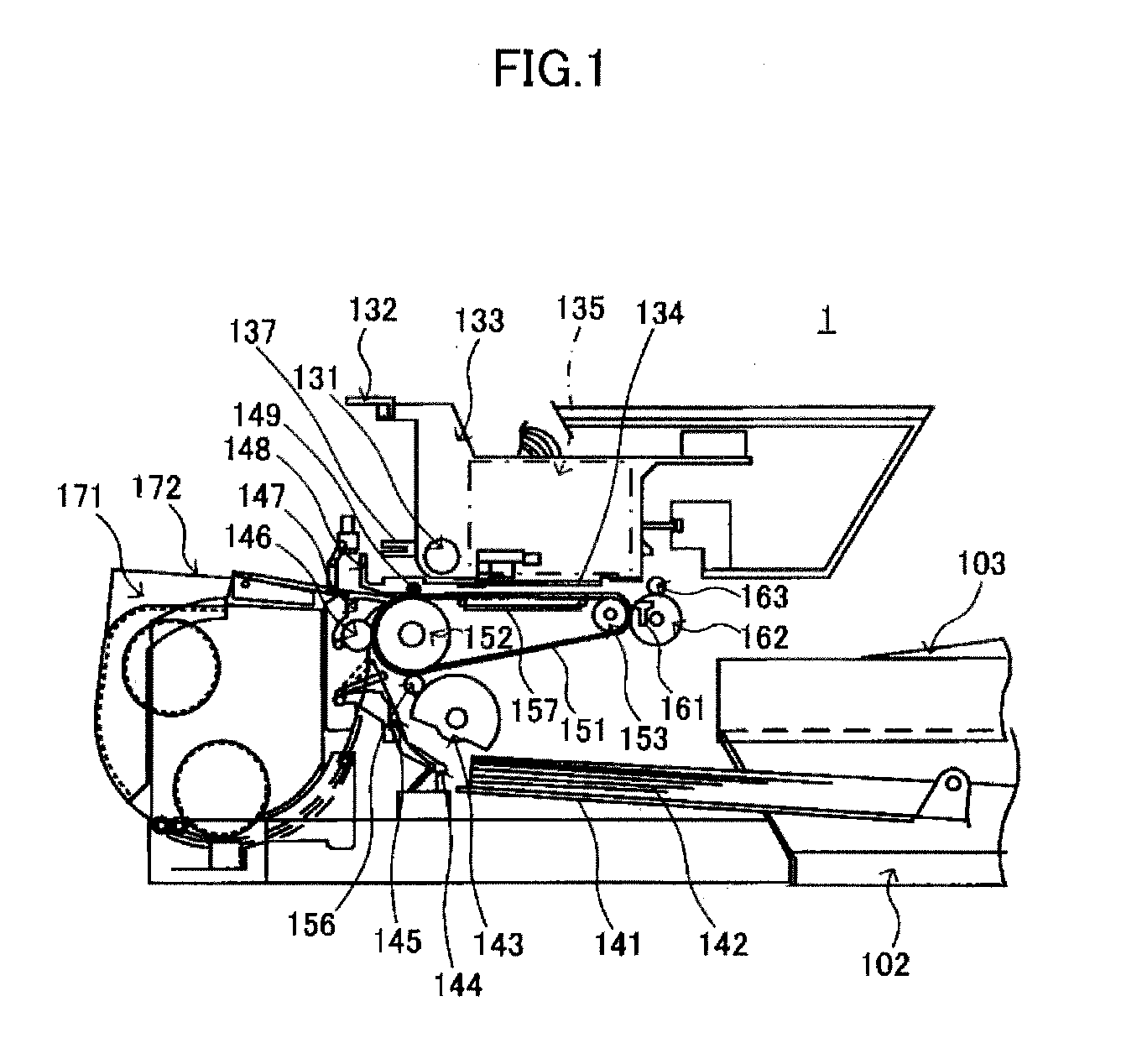
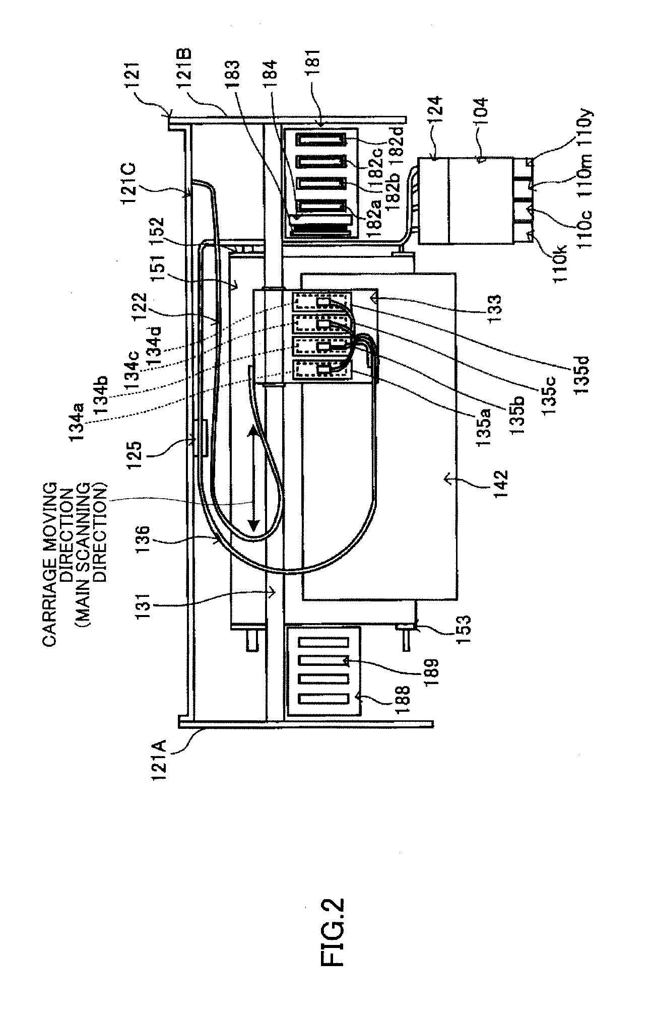
[0068]In an image forming device of this example, the liquid drop ejecting head of Example 1 is mounted on an image formation unit, and the image formation unit forms an image on a medium by ejecting liquid drops to the medium from the liquid drop ejecting head. According to this example, as in the above-described embodiment, the image forming device has good liquid resistance to the printing liquid and can perform stable image formation.


PUM

PropertyMeasurementUnit
depthaaaaaaaaaa
depthaaaaaaaaaa
liquidaaaaaaaaaa

Abstract

A liquid drop ejecting head includes a a nozzle plate to form nozzles, a liquid chamber substrate including one surface bonded to the nozzle plate and forming liquid chambers provided for the nozzles and communicating with the nozzles, a diaphragm bonded to the other surface of the liquid chamber substrate to form a part of each liquid chamber, and a pressure generating unit giving pressure oscillation to the diaphragm in accordance with a liquid drop eject signal to exert pressure on a liquid in each liquid chamber through the diaphragm. In the liquid drop ejecting head, a protection film is formed on an inner side wall of each liquid chamber by a chemical reaction of fluorocarbon and silicon fluoride oxide of a by-product formed on the inner side wall of the liquid chamber with the formation of the liquid chambers in the liquid chamber substrate.

Description

BACKGROUND OF THE INVENTION[0001]1. Field of the Invention[0002]The present disclosure relates to a liquid drop ejecting head which ejects liquid drops from nozzles, an image forming device including the liquid drop ejecting head to form an image on a print medium by ejecting liquid drops, and a method of manufacturing the liquid drop ejecting head.[0003]2. Description of the Related Art[0004]A liquid drop ejecting head which ejects liquid drops from nozzles is used, for example, as a printing head in image forming devices, such as copiers, printers, facsimile devices, plotters, and multi-function peripherals. The image forming device is a device which forms an image on a print medium by ejecting liquid drops to the print medium. In the following, the material of the print medium is not limited to paper, and the print medium used in the image forming devices of the liquid drop ejection type may include all printing sheets (paper), yarn, fibers, textile, leather, metal, plastics, gla...

Claims


Application Information

Patent Timeline
Patent Type & Authority Applications(United States)
IPC IPC(8): B41J2/14B41J2/16
CPCB41J2/14233B41J2/1606B41J2/161B41J2/1623B41J2002/14241B41J2/1628B41J2/1631B41J2/1642B41J2/1646B41J2/1625
Inventor OHNISHI, KOUJIURASAKI, KOHZOHNISHIMURA, MANABU
Owner RICOH KK
Learn More