Nozzle plate, liquid ejecting head, and liquid ejecting apparatus

a liquid ejecting apparatus and nozzle technology, applied in the direction of printing, inking apparatus, etc., can solve the problems of ink drop, ink resistance problem, and film thickness is likely to be large, and achieve good discharge variation, excellent durability, and excellent liquid resistance

Active Publication Date: 2015-01-20
SEIKO EPSON CORP
View PDF6 Cites 1 Cited by
  • Summary
  • Abstract
  • Description
  • Claims
  • Application Information

AI Technical Summary

Benefits of technology

[0009]An object of the invention is to provide a nozzle plate that has excellent liquid resistance on an inner surface of a nozzle opening and a discharge surface, and a liquid ejecting head and a liquid ejecting apparatus using the nozzle plate.
[0011]According to this aspect, the tantalum oxide film that is film-formed by an atomic layer deposition method is uniformly and densely formed even on a narrow area such as an inner circumferential surface of the nozzle opening, and functions effectively as the protective film against a strong alkaline liquid and a strong acid solution since the tantalum oxide film formed by plasma CVD is stacked thereon. Also, since the tantalum oxide film formed by plasma CVD which is a base of the liquid-repellent film is disposed on the tantalum oxide film which is film-formed by the atomic layer deposition method, the adhesive property is excellent when the thick liquid-repellent film excellent in mechanical strength and liquid resistance is disposed.
[0013]It is preferable that a silicon thermal oxide film is formed in a lower layer of the tantalum oxide film formed by the atomic layer deposition. In this manner, liquid resistance can be further improved.
[0014]It is preferable that a liquid-repellent film is stacked on the tantalum oxide film formed by the plasma CVD through annealing of a metal alkoxide film. In this case, liquid repellency of the discharge surface is improved, high liquid resistance is ensured in a part where the liquid-repellent film is not formed in a boundary portion between an inner portion of the nozzle opening and an area in the vicinity of the nozzle opening where the liquid-repellent film is formed, and a problem such as peeling of the liquid-repellent film caused by a problem such as erosion of the silicon substrate by a liquid is addressed.
[0016]According to this configuration, the nozzle plate is excellent in liquid resistance and has no problem of peeling of the liquid-repellent film, and opening variation of the nozzle opening is small, and thus a liquid ejecting head with little discharge variation and excellent in durability can be achieved.
[0017]Still another aspect of the invention is directed to a liquid ejecting apparatus including the liquid ejecting head of the above aspect. According to this, a liquid ejecting apparatus with little discharge variation and excellent in durability can be achieved.

Problems solved by technology

However, there is a case where a uniform film is unlikely to be formed on the inner surface of the nozzle opening, particularly around the vicinity of the discharge surface, and an ink resistance problem is likely to occur when the ink-resistant protective film formed of the metal oxide is disposed by CVD, and where film thickness is likely to be large and not uniform and a problem of non-uniformity of discharged ink drops arises when a sufficient film is to be formed over the entire surfaces.
In a case where the above-described nozzle plate is a nozzle plate in which a nozzle hole is formed on the silicon substrate by using anisotropic etching, there is a case where an adhesive property of the ink protective film causes a problem.
In addition, the base film such as the plasma-polymerized film of the silicone material of JP-A-2004-351923 has a possibility of generating microdefects, and there is a case where a problem such as peeling of the liquid-repellent film arises due to such microdefects.

Method used


Image

  • Nozzle plate, liquid ejecting head, and liquid ejecting apparatus
  • Nozzle plate, liquid ejecting head, and liquid ejecting apparatus
  • Nozzle plate, liquid ejecting head, and liquid ejecting apparatus

Examples


embodiment 1

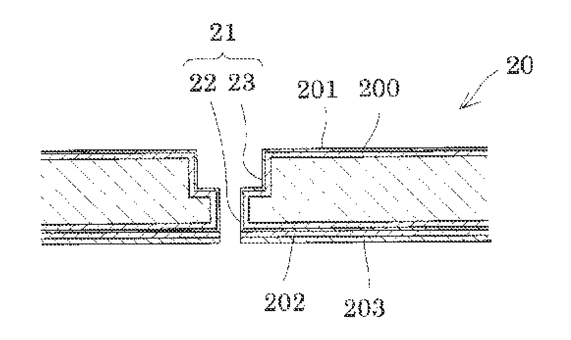
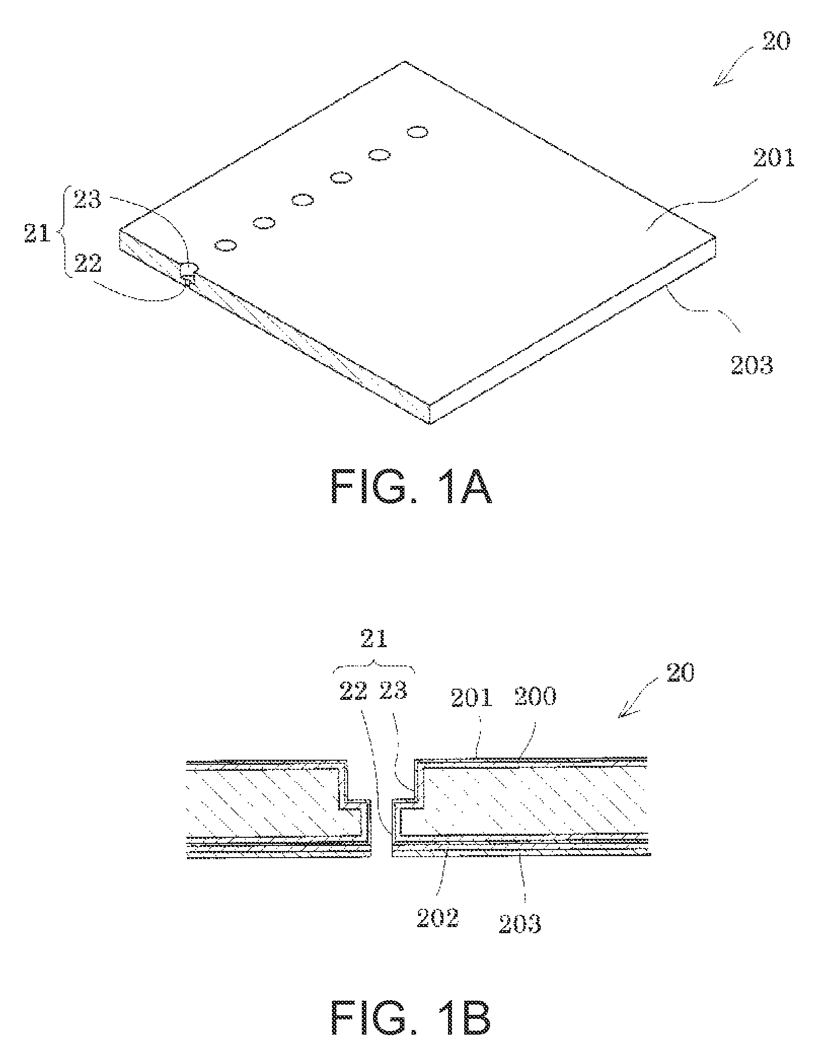
[0025]First, an example of a nozzle plate according to Embodiment 1 of the invention will be described. FIGS. 1A and 1B are a perspective view and an enlarged cross-sectional view of a main part of the nozzle plate according to Embodiment 1.

[0026]As shown in FIGS. 1A and 1B, the nozzle plate 20 is a member formed from a silicon single crystal substrate on which a plurality of nozzle openings 21 are formed in a row with a pitch corresponding to a dot formation density. In this embodiment, a nozzle array is configured such that the number of the nozzle openings 21 arrayed with a pitch of 180 dpi is 180. Each of the nozzle openings 21 is configured to have two successive cylindrical hole portions that are formed by dry etching and have different inner diameters. In other words, the nozzle opening 21 is configured to have a first cylindrical portion 22 that is formed on an ink discharge side in a plate thickness direction of the nozzle plate 20 and has a small inner diameter, and a seco...

embodiment 2

[0047]Hereinafter, an inkjet type recording head that is an example of a liquid ejecting head using the nozzle plate 20 of Embodiment 1 described above will be described.

[0048]FIG. 3 is an exploded perspective view of the ink jet type recording head of this embodiment, FIG. 4A is a plan view of FIG. 3 and FIG. 4B is a cross-sectional view taken along line A-A′ of FIG. 4A, and FIG. 5 is a cross-sectional view taken along line B-B′ of FIG. 4B.

[0049]As shown in the drawings, a passage forming substrate 10 of an ink jet type recording head I which is an example of the liquid ejecting head of this embodiment is formed from, for example, a silicon single crystal substrate in this embodiment. In the passage forming substrate 10, pressure generating chambers 12 that are partitioned by a plurality of partition walls 11 are arranged along a direction in which a plurality of nozzle openings 21 discharging ink of the same color are arranged. Hereinafter, this direction is referred to as an arra...


PUM

PropertyMeasurementUnit
thicknessaaaaaaaaaa
thicknessaaaaaaaaaa
thicknessaaaaaaaaaa

Abstract

A silicon nozzle plate has excellent liquid resistance on an inner surface of a nozzle opening and a discharge surface. A plurality of the nozzle openings are disposed in a silicon substrate of the nozzle plate. A first tantalum oxide film is disposed by atomic layer deposition on both surfaces of the silicon substrate and the inner surface of the nozzle opening, and a second tantalum oxide film that is formed by plasma CVD is stacked on the first tantalum oxide film of the discharge surface.

Description

BACKGROUND[0001]1. Technical Field[0002]The present invention relates to a nozzle plate having a nozzle opening to discharge liquid drops, and a liquid ejecting head and a liquid ejecting apparatus including the nozzle plate.[0003]2. Related Art[0004]In general, an ink jet type recording head known as a representative example of a liquid ejecting head includes a nozzle plate where a plurality of nozzle openings to discharge liquid drops are formed, and a passage forming substrate where a pressure generating chamber communicating with the nozzle opening is formed. In such a liquid ejecting head, a silicon substrate is used in the passage forming substrate and the nozzle plate for an increase in nozzle density, and both thereof are bonded with each other by an adhesive agent.[0005]JP-A-2009-184176 discloses a method for suppressing residue of the ink, in which a surface of a nozzle plate bonded with the passage forming substrate and an inner surface of the nozzle opening are provided ...

Claims


Application Information

Patent Timeline
Patent Type & Authority Patents(United States)
IPC IPC(8): B41J2/045B41J2/45B41J2/16B41J2/14
CPCB41J2002/14491B41J2/1623B41J2/1642B41J2002/14241B41J2/1626B41J2/161B41J2/1433B41J2202/03B41J2/14233B41J2002/14419B41J2/162
Inventor MISAWA, MIDORIGOTO, TAMOTSU
Owner SEIKO EPSON CORP
Why Eureka
Try Eureka