Spark ignition type internal combustion engine

Inactive Publication Date: 2013-10-03
TOYOTA CENT RES & DEV LAB INC
View PDF5 Cites 22 Cited by
  • Summary
  • Abstract
  • Description
  • Claims
  • Application Information

AI Technical Summary

Benefits of technology

[0010]An advantage of the present invention is provision of a spark ignition engine in which the thermal efficiency is improved without worsening the knocking.
[0011]According to one aspect of the present invention, there is provided a spark ignition engine in which a thermal insulation layer is formed over a wall surface, facing an inside of a combustion chamber, of at least a part of base materials forming the combustion chamber, and mixture gas in the combustion chamber is ignited to burn the mixture gas, wherein, for a thermal conductivity λ [W/(m·K)], a thermal diffusivity κ [mm2/s], and a thickness L [μm] of the thermal insulation layer, a relationship:
[0012]According to another aspect of the present invention, there is provided a spark ignition engine in which a thermal insulation layer is formed over a wall surface, facing an inside of a combustion chamber, of at least a part of base materials forming the combustion chamber, and mixture gas in the combustion chamber is ignited to burn the mixture gas, wherein a thickness of the thermal insulation layer is set within a range of greater than or equal to a lower limit thickness and less than or equal to an upper limit thickness, the lower limit thickness being a thickness where an accumulated amount of heat transferred from gas in a cylinder to the wal

Problems solved by technology

However, when the thickness of the thermal insulation layer is increased too much, the temperature of the wall of the combustion chamber which has increased during the combustion stroke is not sufficiently reduced during the expansion and exhaust strokes, and would be at a higher temperature at the start of the intake stroke in the next cycle compared to the configuration without the thermal insulation layer, resulting in an increased amount of heat being transferred from the wall of the combustion chamber to the gas in the cylinder during the intake

Method used


Image

  • Spark ignition type internal combustion engine
  • Spark ignition type internal combustion engine
  • Spark ignition type internal combustion engine

Examples


Embodiment Construction

[0033]A preferred embodiment of the present invention will now be described with reference to the drawings.

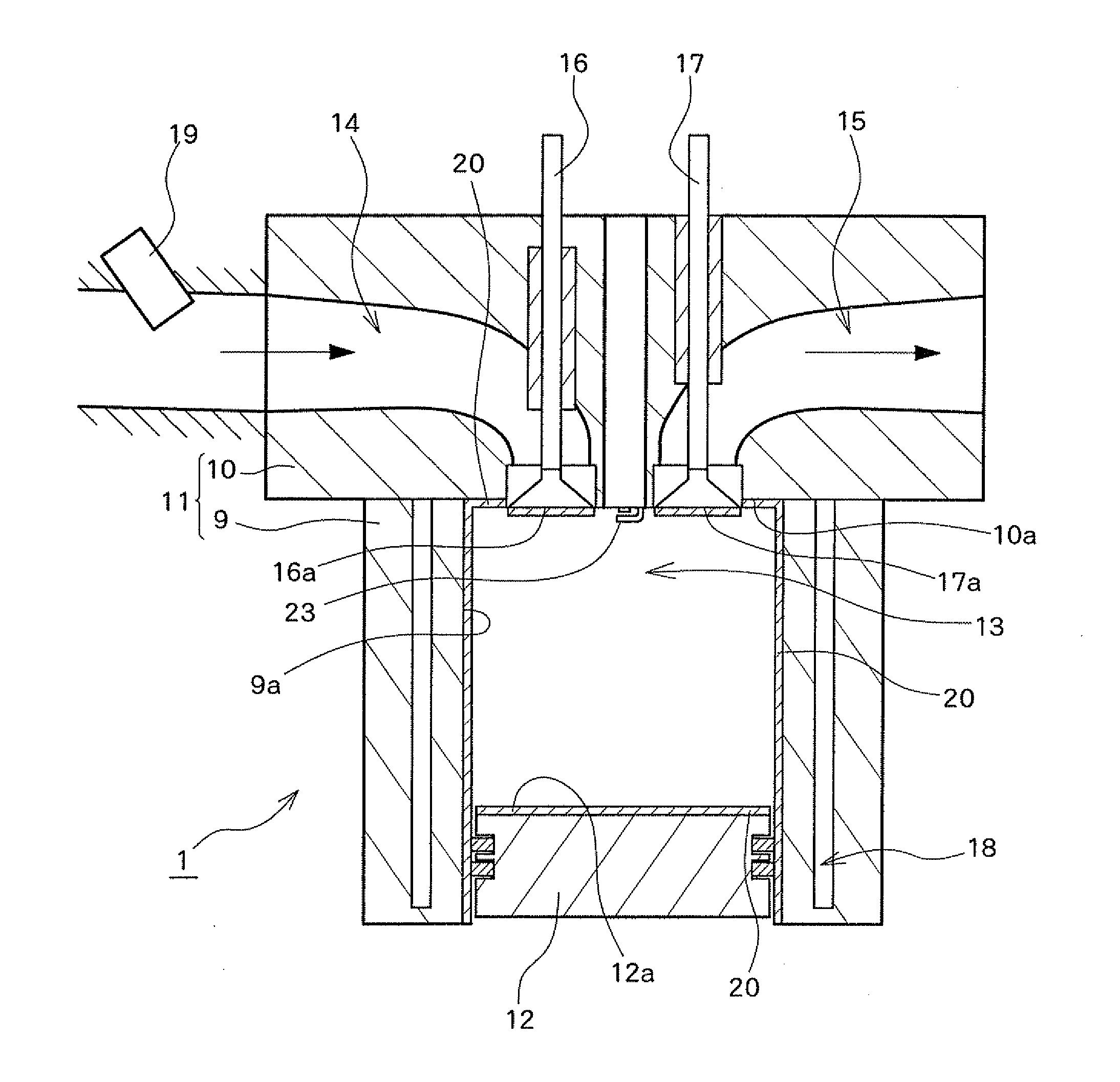
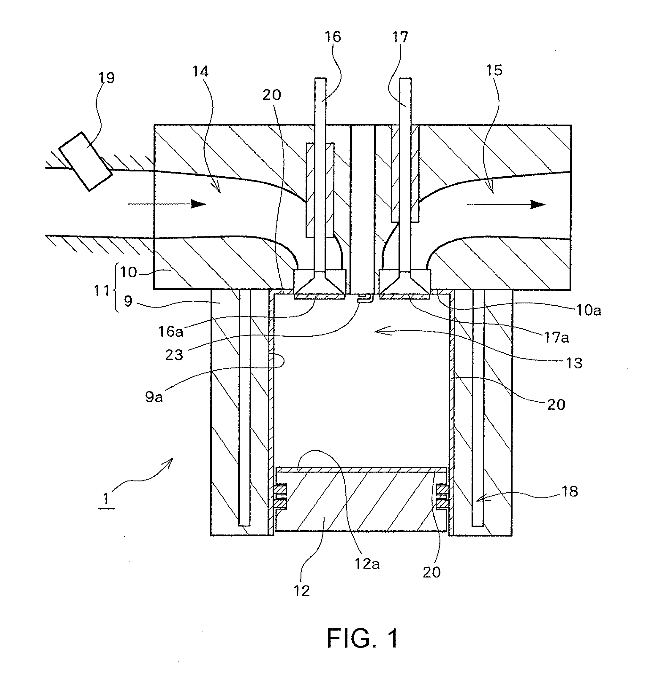
[0034]FIG. 1 is a diagram schematically showing a structure of a spark ignition engine 1 according to a preferred embodiment of the present invention, and schematically showing an internal structure viewed from a direction perpendicular to an axial direction of a cylinder 11. The spark ignition engine 1 according to the present embodiment is formed by, for example, a gasoline engine, and mixture gas in a combustion chamber 13 is spark-ignited by an ignition plug 23, to achieve flame-propagated combustion.

[0035]The internal combustion engine (for example, a gasoline engine) 1 comprises a cylinder block 9 and a cylinder head 10, and the cylinder block 9 and the cylinder head 10 form the cylinder 11. A piston 12 which reciprocates in the axial direction of the cylinder 11 is housed in the cylinder 11. A space surrounded by a top surface 12a of the piston 12, an inner wall surface ...


PUM

PropertyMeasurementUnit
Fractionaaaaaaaaaa
Fractionaaaaaaaaaa
Thicknessaaaaaaaaaa

Abstract

In a spark ignition engine, a thermal insulation thin layer is formed over a wall surface, facing an inside of a combustion chamber, of a base material forming the combustion chamber, and for a thermal conductivity λ [W/(m·K)], a thermal diffusivity κ [mm2/s], and a thickness L [μm] of the thermal insulation thin layer, L≧16.7×λ and L≦207.4×(κ)0.5 are satisfied. With such a configuration, a heat loss Q_total escaping from gas in a cylinder to the wall of the combustion chamber over all strokes can be reduced, and the thermal efficiency can be improved without inducing degradation of knocking due to an increase in an amount of heating Q_intake of the gas in the cylinder during an intake stroke.

Description

PRIORITY INFORMATION[0001]This application claims priority to Japanese Patent Application No. 2012-080138, filed on Mar. 30, 2012, which is incorporated herein by reference in its entirety.BACKGROUND[0002]1. Technical Field[0003]The present invention relates to a spark ignition engine, and in particular to a spark ignition engine in which a thermal insulation layer is formed on a wall surface, facing an inside of a combustion chamber, of at least a part of base materials forming the combustion chamber of the internal combustion engine.[0004]2. Related Art[0005]In order to improve thermal efficiency of an internal combustion engine, a technique has been proposed in which a thermal insulation layer is formed on a wall surface, facing an inside of a combustion chamber, of at least a part of base materials forming the combustion chamber of the internal combustion engine (for example, refer to JP 1-142246 A). In JP 1-142246 A, for example, a thermal insulation layer made of ceramic with ...

Claims


Application Information

Patent Timeline
IPC IPC(8): F02B23/00
CPCF02B23/00F05C2251/048F02F1/00Y02T10/125F01L2301/02F02B77/11F02F1/24F02F3/14F02F2001/008F05C2201/0412F05C2201/0415F05C2203/08F05C2203/0817F05C2203/0843F05C2203/0869F05C2203/0886F05C2203/0895F05C2253/12Y02T10/12
Inventor NOMURA, YOSHIHIROKOSAKA, HIDEMASAKOIKE, MAKOTOWAKISAKA, YOSHIFUMIHOTTA, YOSHIHIRONAKAKITA, KIYOMI
Owner TOYOTA CENT RES & DEV LAB INC
Why Eureka
Try Eureka