
Tunable layered membrane configuration for filtration and selective isolation and recovery devices

Active Publication Date: 2013-10-03
LOCKHEED MARTIN CORP
View PDF14 Cites 51 Cited by
  • Summary
  • Abstract
  • Description
  • Claims
  • Application Information

AI Technical Summary

Benefits of technology

The selective isolation patent makes use of pore control and electrical charge to create an effective porosity that improves the rejection of charged particles in feedwater. This results in increased selectivity of the process.

Problems solved by technology

Reverse osmosis market share is growing but current reverse osmosis technology remains capital and energy intensive, with limitations in product design and performance based upon current polymer filtration membranes.
Such devices are limited in permeability which in turn limits output water per unit area, or flux, and requires increased membrane area and operating pressures.
As such, these filtration devices require frequent cleaning and ultimately replacement.
The limitations in relation to the flux and associated membrane area requirements result in significant capital cost.
The need for high operating pressure devices increase the energy required to operate the filtration device and which further results in degradation of the membrane due to fouling and compaction which also adds to the operating cost.
Although improvements have been made in the filtration media, these are only incremental improvements and do not address the issues raised in regard to limited flux throughput or the requirement for high operating pressures.
In the reverse osmosis technology, the membranes are susceptible to fouling, scaling and compaction.
These materials also have limited chemical and biological resistance with limited methods of cleaning, which in turn relates to the need for frequent replacement of the filtration devices.
Pretreatment is capital intensive and requires plant space, equipment, energy, and chemicals.
Furthermore, current state reverse osmosis membranes in some installations require multiple post treatment stages to achieve the desired product water.
These additional stages require additional plant space and energy consumption.

Method used


Image

  • Tunable layered membrane configuration for filtration and selective isolation and recovery devices
  • Tunable layered membrane configuration for filtration and selective isolation and recovery devices
  • Tunable layered membrane configuration for filtration and selective isolation and recovery devices

Examples


Embodiment Construction

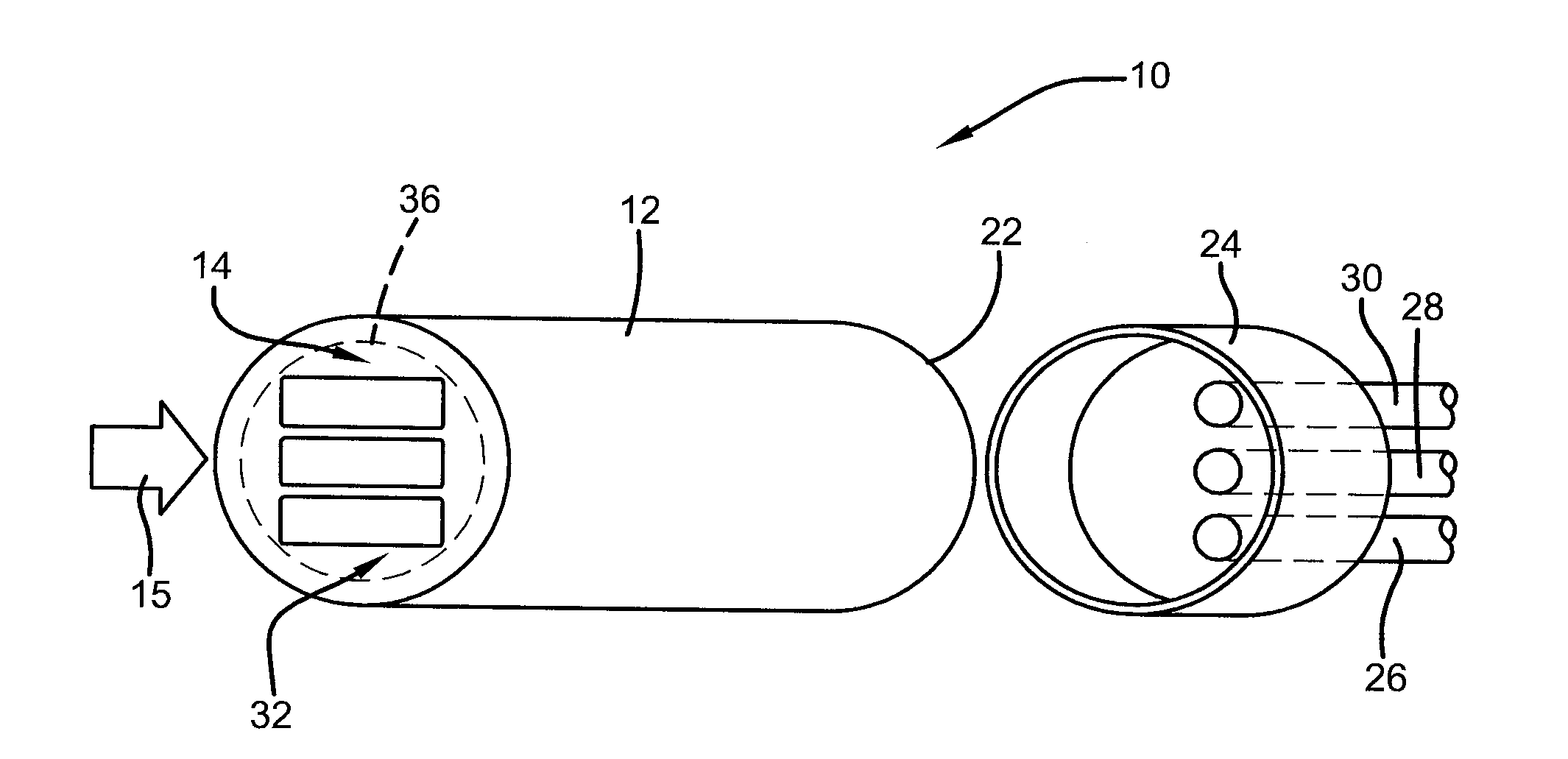
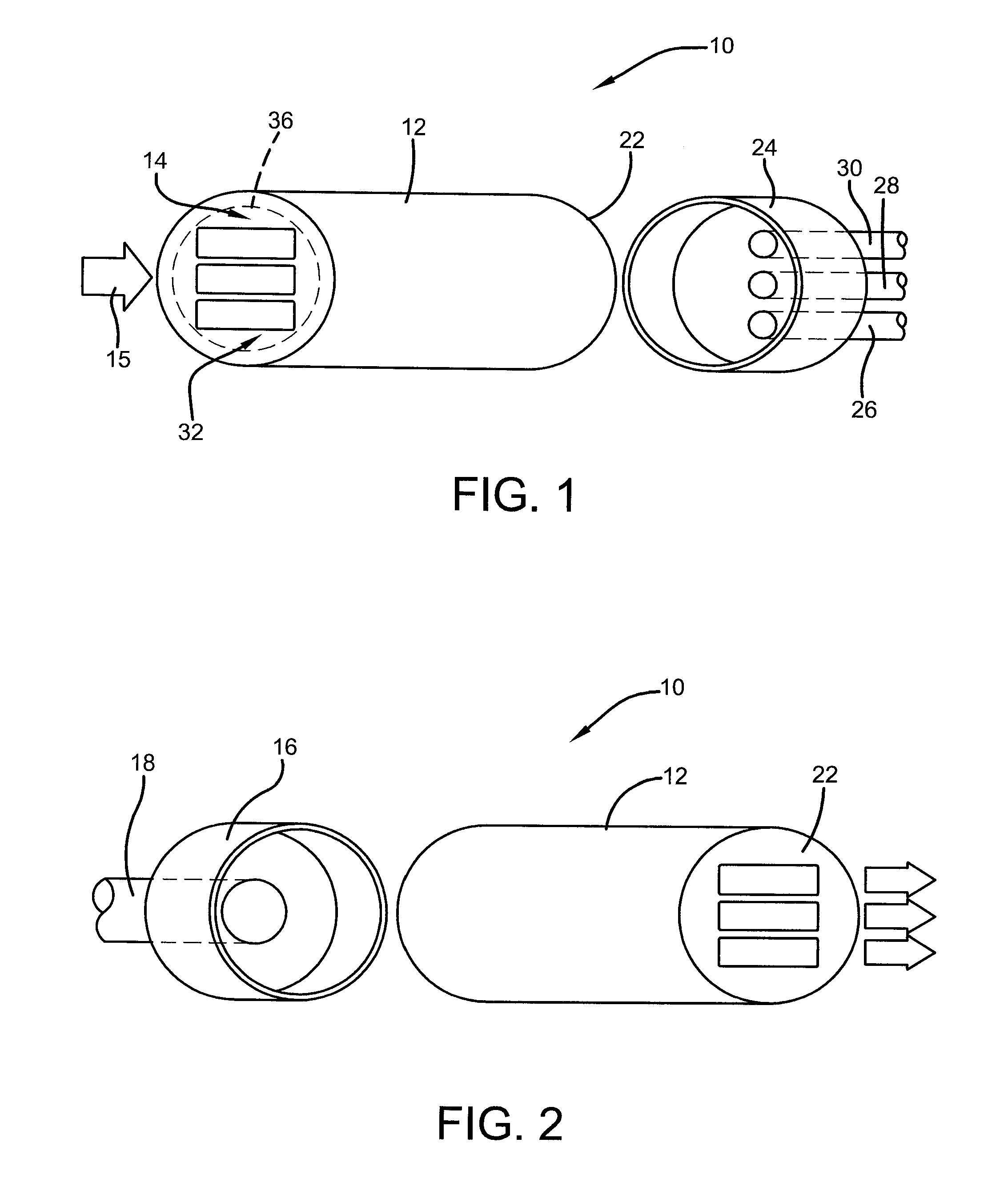
[0031]Referring now to FIGS. 1 and 2, it can be seen that a filtration device is designated generally by the numeral 10. FIG. 1 presents a general perspective cross-sectional view of an inlet side while FIG. 2 presents a perspective general cross-sectional view of an outlet side of the filtration device. The device 10 includes a housing 12 which may be of a cylindrical construction as shown, but other shapes are believed to be possible depending upon end-use applications. In any event, the housing 12 includes an inlet 14 which receives feedwater 15 or other fluid for filtration or selective isolation and recovery. Although the term feedwater is used throughout this description, it will be appreciated that the feedwater or fluid material provided to the filtration device may not include water. As used herein, feedwater refers to the medium that includes components supplied to the filtration device for separation and removal.

[0032]Attached to the inlet is an inlet cap 16 which provide...


PUM


Abstract

A tunable membrane configuration for a filtration or selective fluidic isolation and recovery device includes a housing having an inlet at one end and an outlet at an opposite end with an opening extending from the inlet to the outlet. An internal support structure is maintained in the opening, and layered filtration media is carried by the internal support structure, the media separating feedwater received at the inlet into at least three separate output flows.

Description

CROSS-REFERENCE TO RELATED APPLICATIONS[0001]This application claims priority of U.S. Provisional Application Ser. No. 61 / 617,264 filed Mar. 29, 2012, which is incorporated herein by reference.TECHNICAL FIELD[0002]Generally, the present invention relates to a membrane configuration design for filtration and selective fluidic isolation and recovery devices. Specifically, the present invention relates to a layered membrane configuration for a filtration or selective fluidic isolation and recovery device. More particularly, the present invention is directed to a layered configuration of materials that include at least one high flux, high selectivity membrane. The layers may be arranged in a planar, spiral wound or other alternate multiple pass configuration in dead end flow or cross flow.BACKGROUND ART[0003]Currently, nearly half of the online capacity of desalinated water is achieved through a reverse osmosis filtering process. Reverse osmosis market share is growing but current rever...

Claims


Application Information

Patent Timeline
IPC IPC(8): B01D71/02
CPCB01D61/022C02F1/444B01D61/027B01D61/12B01D63/082B01D65/08B01D69/06B01D2319/022B01D2319/06B01D2321/22B01D2325/02B01D71/021C02F1/44C02F1/441C02F1/442B01D61/025Y02A20/131B01D61/026B01D71/0211B01D61/147B01D61/145B01D2313/12B01D61/029
Inventor FLEMING, SHAWN P.
Owner LOCKHEED MARTIN CORP
Learn More