
Laser processing using an astigmatic elongated beam spot and using ultrashort pulses and/or longer wavelengths

a laser processing and astigmatic elongation technology, applied in the field of laser processing, can solve the problems of narrower streets between the devices, limited wavelength, pulse duration, and existing systems for scribing using an astigmatic elongated beam spo

Inactive Publication Date: 2013-10-03
IPG PHOTONICS CORP
View PDF246 Cites 25 Cited by
  • Summary
  • Abstract
  • Description
  • Claims
  • Application Information

AI Technical Summary

Benefits of technology

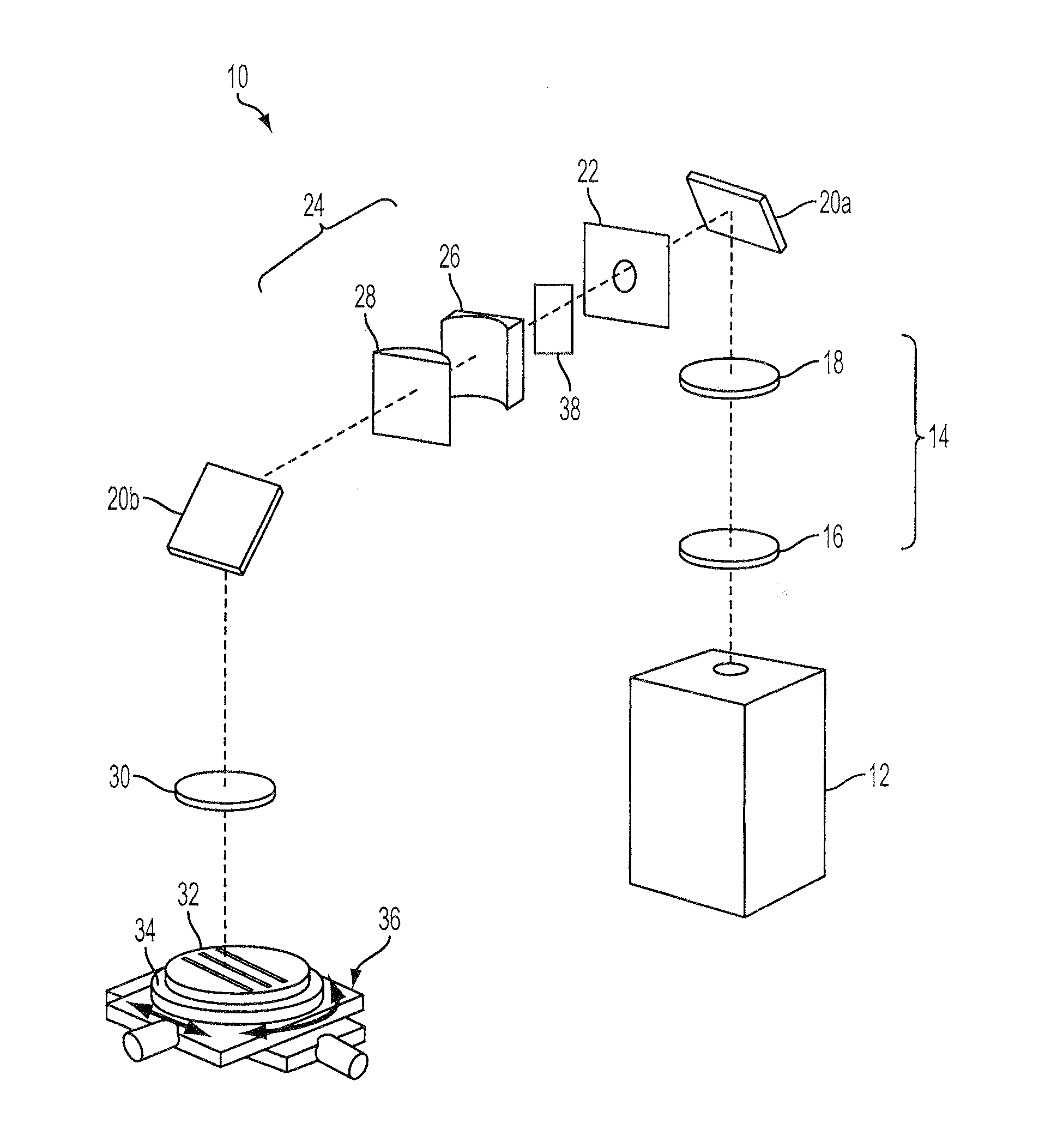
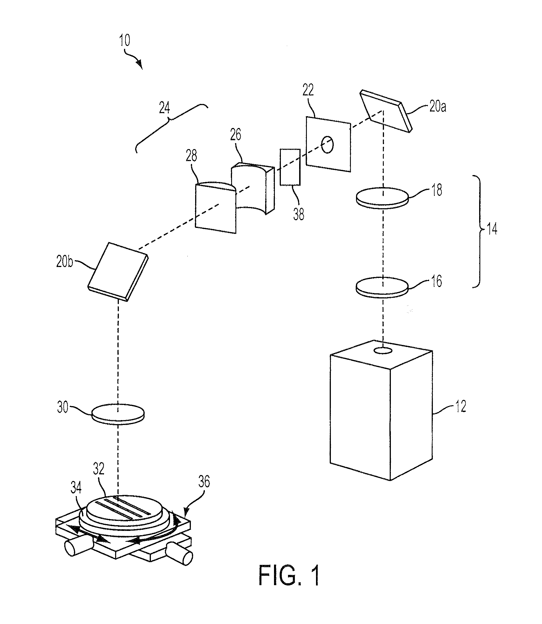
The present invention relates to a laser processing system that uses an astigmatic elongated beam spot to perform laser scribing, such as in the manufacturing of semiconductor devices. The invention provides a beam delivery system with astigmatic focal point optics that can modify the laser beam to improve processing speed and accuracy while minimizing heat damage. The invention also includes a method for sequentially modifying the laser beam to further improve processing precision. The use of ultrashort pulses and longer wavelengths in the visible and IR ranges makes the invention more versatile and adaptable to different materials, wavelengths, and pulse durations. Overall, the invention allows for improved laser scribing with reduced damage to the devices and increased yield per wafer.

Problems solved by technology

Positioning the devices more closely on the semiconductor wafer results in narrower streets between the devices.
Although such methods have provided advantages over other techniques for forming a line beam to scribe a workpiece, existing systems for scribing using an astigmatic elongated beam spot have been limited to certain materials, wavelengths, and pulse durations.
Lasers producing ultrashort pulses and / or longer wavelengths in the visible and IR ranges have become commercially available but have presented challenges in certain laser scribing applications because of the desire to maintain high laser processing speeds and accuracy while minimizing melting and other heat damage.

Method used


Image

  • Laser processing using an astigmatic elongated beam spot and using ultrashort pulses and/or longer wavelengths
  • Laser processing using an astigmatic elongated beam spot and using ultrashort pulses and/or longer wavelengths
  • Laser processing using an astigmatic elongated beam spot and using ultrashort pulses and/or longer wavelengths

Examples


Embodiment Construction

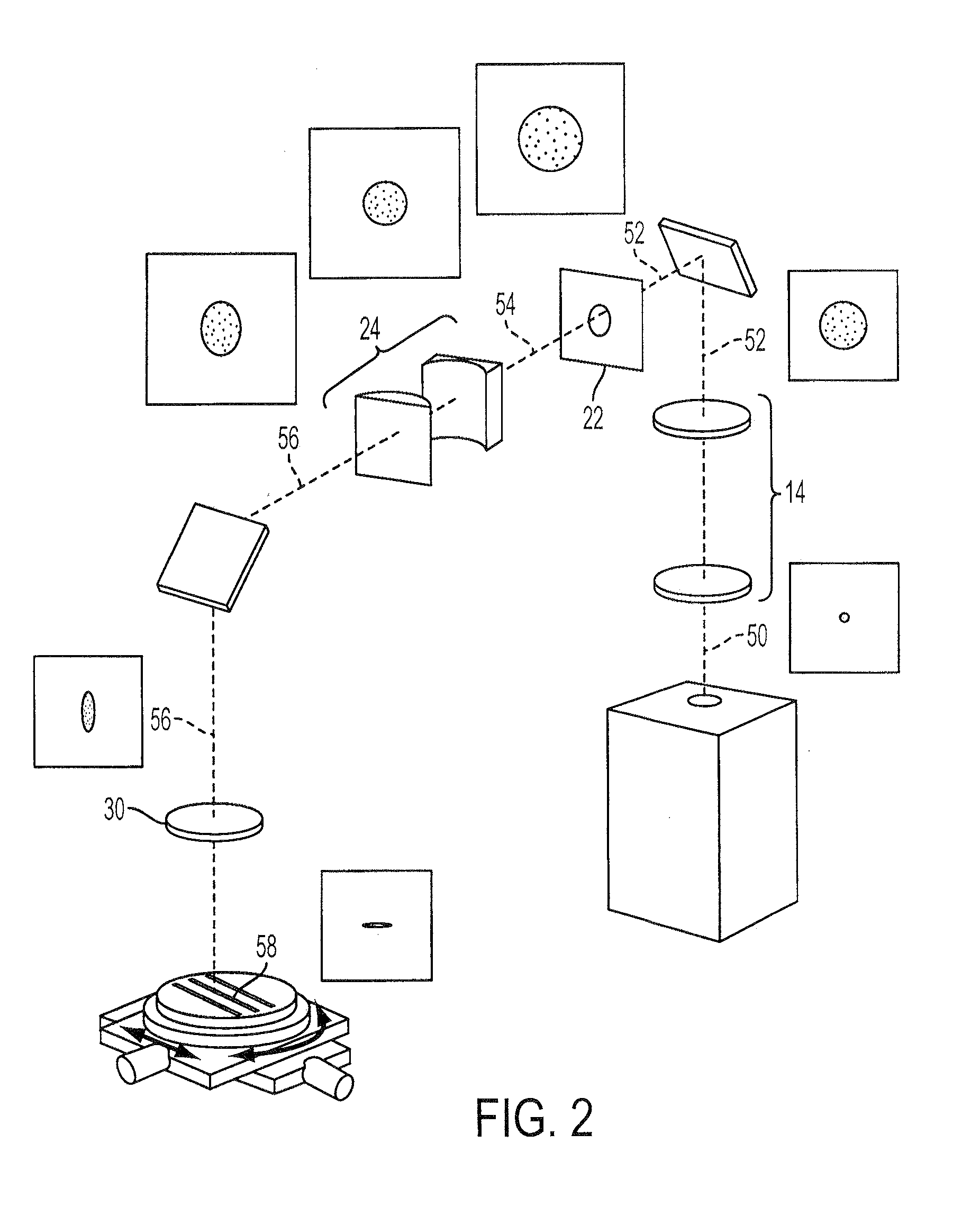
[0016]An adjustable astigmatic elongated beam spot may be formed from a laser beam having ultrashort laser pulses and / or longer wavelengths, consistent with embodiments described herein, to machine substrates made of a variety of different materials. The laser beam may be generated with pulses having a pulse duration of less than 1 ns and / or having a wavelength greater than 400 nm. The laser beam is modified to produce an astigmatic beam that is collimated in a first axis and converging in a second axis. The astigmatic beam is focused to form the astigmatic elongated beam spot on a substrate, which is focused on the substrate in the first axis and defocused in the second axis. The astigmatic elongated beam spot may be adjusted in length to provide an energy density sufficient for a single ultrashort pulse to cause cold ablation of at least a portion of the substrate material. Thus, the adjustable astigmatic elongated beam spot allows the energy density to be adjusted to avoid losing...


PUM

PropertyMeasurementUnit
wavelengthaaaaaaaaaa

Abstract

An adjustable astigmatic elongated beam spot may be formed from a laser beam having ultrashort laser pulses and / or longer wavelengths to machine substrates made of a variety of different materials. The laser beam may be generated with pulses having a pulse duration of less than 1 ns and / or having a wavelength greater than 400 nm. The laser beam is modified to produce an astigmatic beam that is collimated in a first axis and converging in a second axis. The astigmatic beam is focused to form the astigmatic elongated beam spot on a substrate, which is focused on the substrate in the first axis and defocused in the second axis. The astigmatic elongated beam spot may be adjusted in length to provide an energy density sufficient for a single ultrashort pulse to cause cold ablation of at least a portion of the substrate material.

Description

CROSS-REFERENCE TO RELATED APPLICATIONS[0001]This application is a continuation-in-part of co-pending U.S. patent application Ser. No. 13 / 422,190, filed Mar. 16, 2012, which is a continuation-in-part of U.S. patent application Ser. No. 12 / 962,050 filed Dec. 7, 2010, which claims the benefit of U.S. Provisional Patent Application Ser. No. 61 / 267,190 filed Dec. 7, 2009, both of which are incorporated herein by reference.TECHNICAL FIELD[0002]This invention relates to laser processing, and more particularly, relates to laser processing, such as scribing, using an astigmatic elongated beam spot formed from a solid-state laser producing ultrashort pulses and / or longer wavelengths in the visible or IR ranges.BACKGROUND INFORMATION[0003]Lasers are commonly used to process or machine a workpiece, for example, by cutting or scribing a substrate or semiconductor wafer. In semiconductor manufacturing, for example, a laser is often used in the process of dicing a semiconductor wafer such that in...

Claims


Application Information

Patent Timeline
Patent Type & Authority Applications(United States)
IPC IPC(8): B23K26/00
CPCB23K26/041B23K26/0608B23K26/0676B23K26/0738B23K26/367B23K2201/40B23K26/0066B23K26/0823B23K26/4075B23K26/042B23K26/364B23K26/40B23K2101/40B23K2103/50B23K26/352
Inventor SERCEL, JEFFREY P.MENDES, MARCO
Owner IPG PHOTONICS CORP
Learn More