Load bearing panel assembly

a technology of load bearings and panels, applied in mechanical equipment, transportation and packaging, other domestic objects, etc., can solve the problems of weight penalty, limiting the open compartment space available, and non-reinforced twin sheet panels that cannot resist loading forces, etc., to achieve good energy absorption, low yield, and high strength

Inactive Publication Date: 2013-10-03
CENTURY PLASTICS LLC
View PDF4 Cites 10 Cited by
  • Summary
  • Abstract
  • Description
  • Claims
  • Application Information

AI Technical Summary

Benefits of technology

[0004]A panel assembly and method for making the panel assembly is provided herein. The panel assembly described herein includes at least one reinforcing assembly which is made of a high strength material having a low yield to tensile strength ratio for good energy absorption and a reduced weight and thin profile, such that the panel assembly may be configured with light weight and a low profile to minimize protrusion of the panel structure into an opening or compartment enclosed by the panel. The panel assembly, in a non-limiting example, is configured as a floor panel assembly for a vehicle floor, and includes a reinforcing assembly configured to traverse the panel such that the reinforcing assembly extends laterally

Problems solved by technology

Panels of non-reinforced twin sheet construction may not resist loading forces or may warp or distort in high temperature operating environments.
Floor panels strengthened by adding a matrix or grid of reinforcing materials, and/or by increasing the depth of the panel profile or the thickness of the panel are disadvantaged by volume and weight added to the floor panel

Method used


Image

  • Load bearing panel assembly
  • Load bearing panel assembly
  • Load bearing panel assembly

Examples


Embodiment Construction

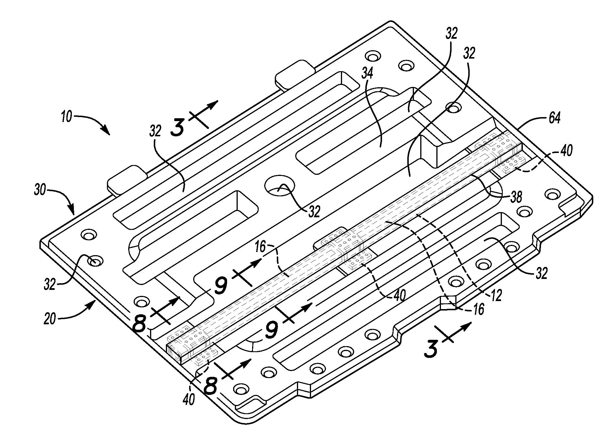
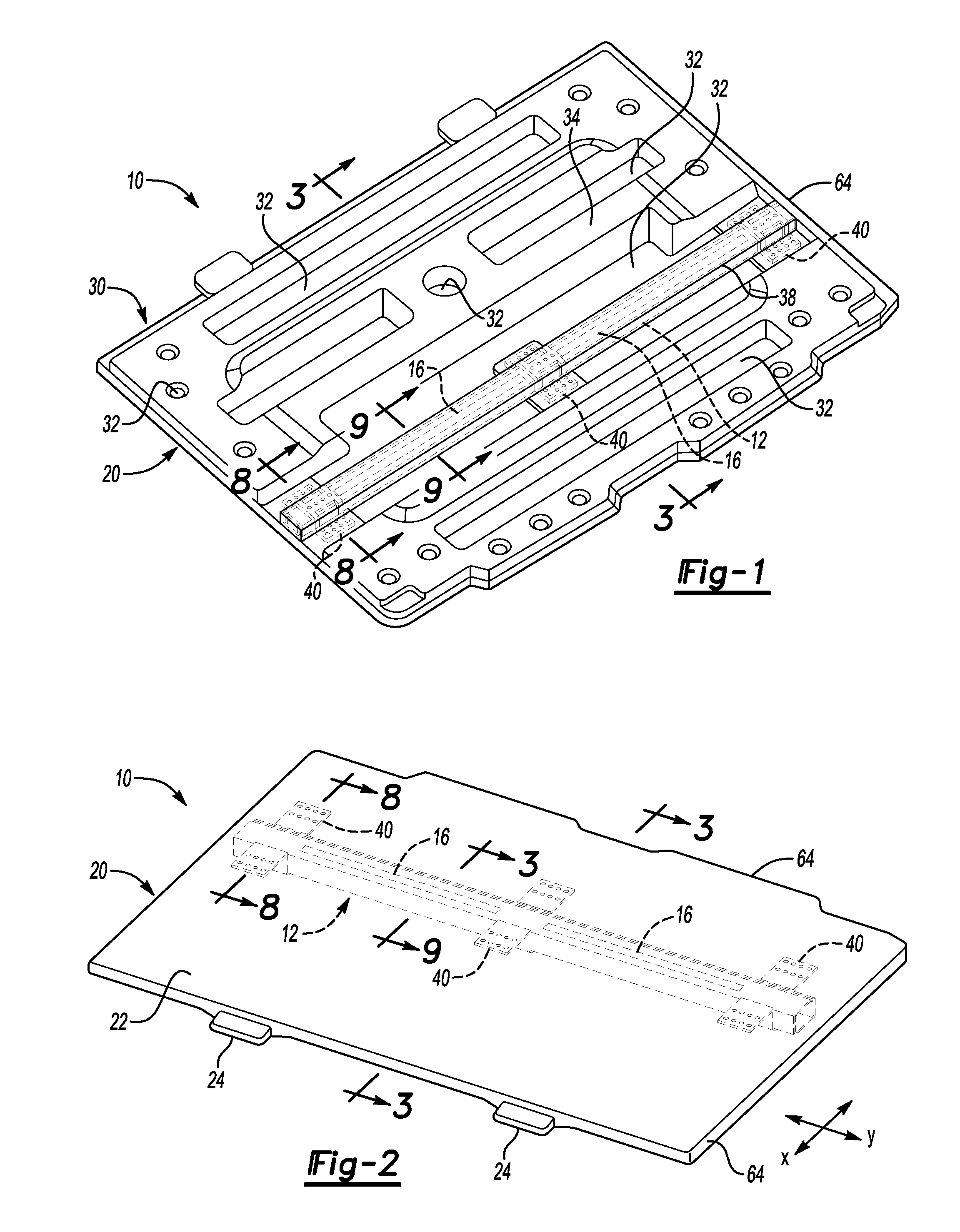
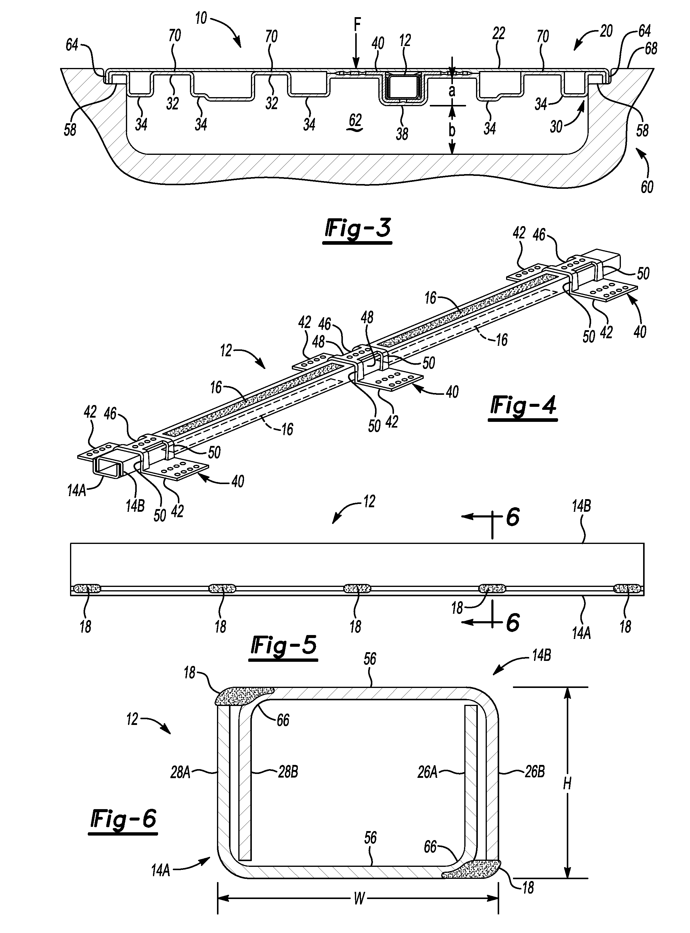
[0017]Referring to the drawings wherein like reference numbers represent like components throughout the several figures, the elements shown in FIGS. 1-9 are not necessarily to scale or proportion. Accordingly, the particular dimensions and applications provided in the drawings presented herein are not to be considered limiting. Referring to FIGS. 1 and 2, generally indicated at 10 is a load bearing panel assembly including a first panel generally indicated at 20 and a second panel generally indicated at 30. The first panel 20 may be configured as an outer panel or appearance panel, such that when the panel assembly 10 is in an installed position, the first panel 20 is outwardly facing relative to an opening or compartment enclosed by the panel assembly 10. The second panel 30 may be configured as an inner panel or support panel, such that when the panel assembly 10 is in an installed position, the second panel 30 is inwardly facing relative to an opening or compartment enclosed by t...


PUM

PropertyMeasurementUnit
Massaaaaaaaaaa
Depthaaaaaaaaaa
Weightaaaaaaaaaa

Abstract

A panel assembly includes at least one reinforcing assembly made of a high strength material having a low yield to tensile strength ratio for energy absorption and reduced weight and profile. The panel assembly may be light-weight with a low profile to minimize protrusion into an opening or compartment enclosed by the panel. The panel assembly may be a floor panel assembly for a vehicle floor. The reinforcing assembly may traverse the panel such that the reinforcing assembly extends laterally, e.g., cross-vehicle, relative to the longitudinal axis of the vehicle body. A method of making the panel assembly may include forming the reinforcing assembly by joining a plurality of metal channel members in a nested arrangement with a plurality of welds to provide a structural assembly with good bending resistance loads imposed on the panel assembly including knee loads. The channel members may be made of a dual phase steel.

Description

CROSS-REFERENCE TO RELATED APPLICATION[0001]This application claims the benefit of U.S. Provisional Application No. 61 / 619,592, filed Apr. 3, 2012, which is hereby incorporated by reference in its entirety.TECHNICAL FIELD[0002]The present invention relates generally to a load bearing panel assembly.BACKGROUND[0003]A panel assembly may be used to enclose a structure which may define an opening or compartment which is to be covered by the panel. The panel may be configured to withstand a force or load imposed on the panel without failing and / or exceeding a maximum deflection. Panel assemblies are used in vehicles to enclose various structures. For example, door panels configured to withstand bending and deflection forces are used to enclose door structures. In another example, a floor panel may be positioned in a floor, trunk, storage, or cargo space of a vehicle to enclose a compartment used to enclose or store one or more vehicle components, such as a spare tire or vehicle jack, or ...

Claims


Application Information

Patent Timeline
IPC IPC(8): B62D25/02E04B2/00
CPCE04C2/44B60R13/01B62D25/02B62D65/02E04C2/38Y10T156/1002B62D25/00F16B2/22F16B5/06B29C65/70B29L2031/30B29C43/18B29C51/08B29K2023/06B29K2023/12B29K2995/0077B29L2031/3005B60R13/011
Inventor MARCHESANO, JOSEPH WILLIAMSAUR, CALVIN ANTHONY
Owner CENTURY PLASTICS LLC
Why Eureka
Try Eureka