Eureka AIR delivers breakthrough ideas for toughest innovation challenges, trusted by R&D personnel around the world.

Electric motor driving apparatus having failure detection circuit, and failure detection method for the electric motor driving apparatus having failure detection circuit

Active Publication Date: 2013-10-03
MITSUBISHI ELECTRIC CORP
View PDF4 Cites 24 Cited by
  • Summary
  • Abstract
  • Description
  • Claims
  • Application Information

AI Technical Summary

Benefits of technology

The present invention provides an electric motor driving apparatus with a failure detection circuit that can detect failure of the DC current detection circuit, even during normal operation, regardless of the rotation rate of the electric motor. The failure detection circuit includes a bridge circuit, a PWM control circuit, a PWM signal generation circuit, a DC current detection circuit, a phase current calculation circuit, and a failure detection circuit. The failure detection circuit determines failure of the DC current detection circuit from the DC current detected values in a zero voltage vector period in which the high-potential-side arms or low-potential-side arms of the bridge circuit are all ON. The failure detection method involves the same processings and can detect failure of each DC current detection circuit, regardless of the rotation rate of the electric motor.

Problems solved by technology

In electric motor control, if a current sensor for detecting DC current on a DC power supply side or output phase current has failed, an electric motor cannot be controlled.

Method used


Image

  • Electric motor driving apparatus having failure detection circuit, and failure detection method for the electric motor driving apparatus having failure detection circuit
  • Electric motor driving apparatus having failure detection circuit, and failure detection method for the electric motor driving apparatus having failure detection circuit
  • Electric motor driving apparatus having failure detection circuit, and failure detection method for the electric motor driving apparatus having failure detection circuit

Examples


first embodiment

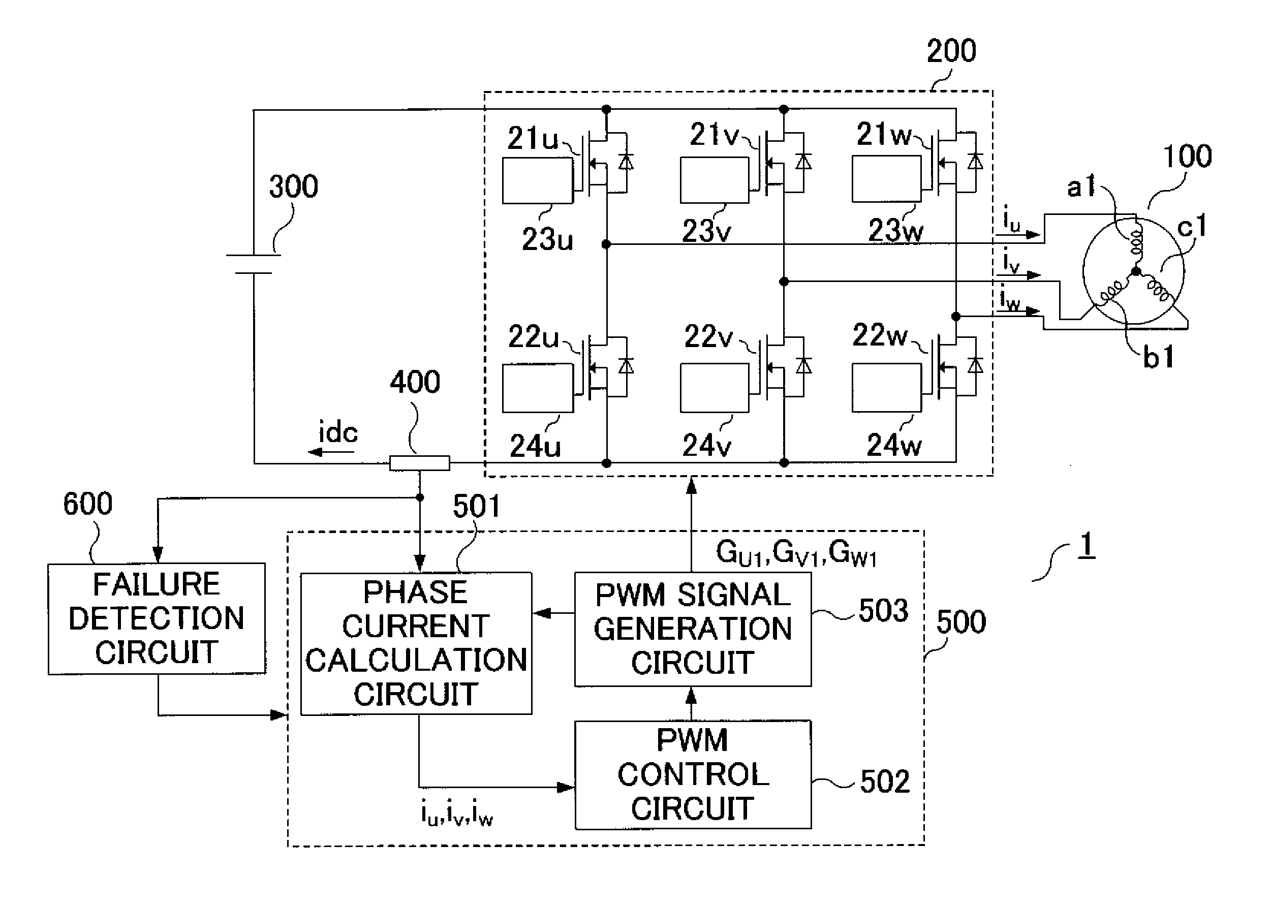
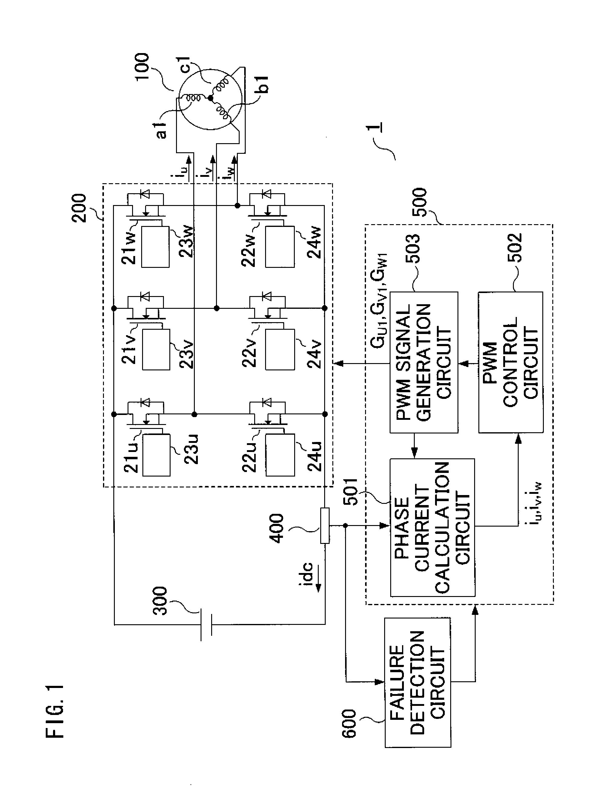
[0023]The first embodiment relates to an electric motor driving apparatus having a failure detection circuit, the electric motor driving apparatus including: a bridge circuit which drives a three-phase winding electric motor; a DC power supply; a PWM control circuit; a PWM signal generation circuit; a DC current detection circuit; a phase current calculation circuit; and a failure detection circuit, and to a failure detection method for the electric motor driving apparatus having a failure detection circuit. The failure detection circuit determines failure of the DC current detection circuit from DC current detected values in a zero voltage vector period in which high-potential-side arms of the bridge circuit are all ON and in a zero voltage vector period in which low-potential-side arms of the bridge circuit are all ON.

[0024]Hereinafter, the configuration and operation of the first embodiment of the present invention will be described based on FIG. 1 which is a system configuration...

second embodiment

[0088]An electric motor driving apparatus having a failure detection circuit according to the second embodiment corresponds to the case where the invention described in the first embodiment is applied to a multiplex-winding electric motor.

[0089]The second embodiment relates to an electric motor driving apparatus having a failure detection circuit, the electric motor driving apparatus including: a plurality of bridge circuits which drive a multiplex-winding electric motor; a DC power supply; a PWM control circuit; a PWM signal generation circuit; a plurality of DC current detection circuits; a phase current calculation circuit; and a failure detection circuit. The failure detection circuit determines failure of each DC current detection circuit from the DC current detected values in a zero voltage vector period in which high-potential-side arms of the corresponding bridge circuit are all ON and in a zero voltage vector period in which low-potential-side arms of the corresponding brid...


PUM


Abstract

An electric motor driving apparatus having a failure detection circuit includes: a bridge circuit driving an electric motor; a PWM control circuit generating voltage instruction for driving the electric motor; a PWM signal generation circuit generating a PWM signal; a DC current detection circuit detecting DC current of the bridge circuit; a phase current calculation circuit calculating output phase current of the bridge circuit, based on the DC current and PWM signal; and a failure detection circuit detecting failure of the DC current detection circuit. The failure detection circuit determines failure of the DC current detection circuit from the DC current detected values in a zero voltage period in which the high-potential-side arms of the bridge circuit are all ON and in a zero voltage period in which the low-potential-side arms are all ON.

Description

BACKGROUND OF THE INVENTION[0001]1. Field of the Invention[0002]The present invention relates to an electric motor driving apparatus, having a failure detection circuit, which drives a three-phase-winding electric motor or a multiplex-winding electric motor.[0003]2. Description of the Background Art[0004]In electric motor control, if a current sensor for detecting DC current on a DC power supply side or output phase current has failed, an electric motor cannot be controlled. Therefore, an electric motor driving apparatus needs to determine whether or not the current sensor has failed.[0005]As a method for detecting failure of the current sensor, a method is disclosed in which DC current is detected by a current sensor connected to a DC power supply side, output phase current is calculated based on the detection, and failure of the current sensor is detected in a zero voltage vector period (for example, Patent Document 1).[0006]Patent Document 1: Japanese Laid-Open Patent Publication...

Claims


Application Information

Patent Timeline
IPC IPC(8): H02K11/00H02P23/00H02P23/07H02P27/06H02P27/08
CPCH02K11/001H02P23/0095H02M2001/0009H02P29/021H02M7/5395H02P27/08H02P29/0241H02M1/0009
Inventor NAKANO, KOSUKEKOJIMA, TETSUYAAZUMA, SATOSHIKEZOBO, ISAOTAKIGUCHI, RYUICHI
Owner MITSUBISHI ELECTRIC CORP
Why Eureka
Eureka Blog
Learn More